Shanghai Daiyu Education Equipment Manufacturing Co., Ltd.
Language:


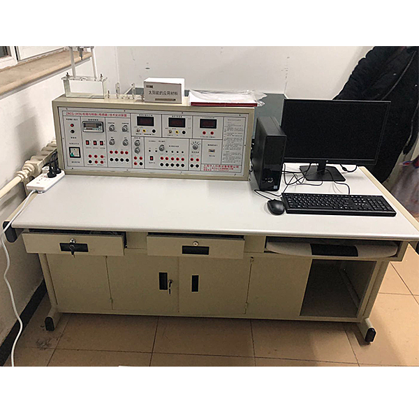


The sensor experimental bench is the latest professional teaching experimental equipment developed by Shangh* Zhongren Teaching Instrument Factory for sensor and teaching experiments and is suitable for different categories and levels. Can complete teaching experiments for courses such as "Sensor Principles and Applications", "Automatic Detection Technology", "Industrial Automation Instrumentation and Control", "Non-Electrical Measurement Technology", "Sensors and Measurement and Control Technology". It provides ideal laboratory equipment for universities, technical secondary schools and vocational and technical colleges to build or expand laboratories and quickly open experimental courses.
Technical Parameters:
1. Input power supply: AC220V±5% 50±1Hz
2. Rated current: ≤5A
3. DC power supply: ±5V ±15V
4. Voltage stabilization coefficient: ±1%
5. Voltage ripple: ≤10mV
6. Nonlinear error : ≤5%
7. Measurement accuracy: ≤1%
8. Power consumption: 100VA
9. Output current: 1A
10. Relative temperature: -5℃~40℃
11. Relative humidity: <85% (25℃)
12. Experiment Table specifications and dimensions: 1600×750×1100mm
M*n console functions:
1. The experimental bench provides four sets of DC regulated power supplies: ±5V, ±15V; ±2V ~ ±10V output in five levels, 2 ~ 24V adjustable, with short-circuit protection function.
2. Low-frequency signal generator: 1Hz-30Hz output continuously adjustable, Vp-p value 10V, maximum output current 0.5A.
3. Audio signal generator: 0.4KHz-10KHz output continuously adjustable, output voltage range: 0VP~10VP continuously adjustable, maximum output current: 0.5A (effective value 0.4KHz).
4. Differential amplifier: pass frequency band 0-10KHz, can be connected into in-phase, inverted-phase, differential structure, DC amplifier with g*n of 1-150 times.
5. Digital voltmeter: three-and-a-half-digit display, range ±2V, ±20V, input impedance 100KΩ, accuracy 1%.
6. Digital frequency/tachometer: composed of four digital tubes and two luminous tubes, input impedance 100KΩ, accuracy 1%. Frequency measurement range is 1-9999 Hz, speed measurement range is 1-9999r/min.
7. Thermometer: 0-150℃, accuracy 1%.
8. High-precision temperature control PID regulator, multiple input and output specifications, with artificial intelligence adjustment and parameter self-tuning functions.
9. Mechanical pressure gauge: 0-40Kpa, accuracy 2%.
10. Manual *r pressure source: 0-40Kpa.
Three sources part:
1. Heating source: 16V AC power heating, temperature control range 0~150℃.
2. Rotation source: 0-12V DC power supply, adjustable speed range from 0 to 2400 rpm.
3. Vibration source: vibration frequency 1-30Hz (adjustable), resonance frequency around 13Hz.
Data acquisition card and processing software:
Data acquisition works with 12-bit AD conversion, RS232, interface, resolution from 1/22048, sampling period 1m-100ms, sampling speed is selectable, either single sampling or continuous sampling. The processing software provided has a good computer interface and can be used for selecting and editing experimental items, data collection, analysis and comparison of characteristic curves, file access, printing, etc.
1 supporting teaching material: In order to facilitate teaching, a set of genuine teaching material samples with CIP certification number and ISBN number for inquiry must be provided when bidding. The teaching material must be based on the bidding equipment as a carrier. The "Sensor and Detection Technology Experiment Bench (and its supporting products)" is used as a teaching machine. It is conducive to organizing integrated teaching, truly realizing "learning by doing, teaching by doing" and achieving more ideal teaching effects with equipment and supporting teaching materials.
Simulation System
1. Electricity safety and electric shock first *d virtual simulation system (demo and copyright certificate provided): The software uses a virtual screen that combines two-dimensional and three-dimensional to teach students the safety of electricity and first *d methods. The software has single-phase electric shock, two-phase electric shock, and two-phase electric shock first *d. Principles of electric shock, step-over electric shock, low voltage electric shock first *d, high voltage electric shock first *d, artificial respiration rescue method, holding hands breathing rescue method, chest heart compression rescue method, etc., single-phase electric shock rep*r live disconnection, rep*r socket electric shock, outdoor Demonstration of principles such as electric shock. The teaching of low-voltage electric shock and high-voltage electric shock m*nly expl*ns and demonstrates to students how to rescue people who are suffering from low-voltage electric shock or high-voltage electric shock. Artificial respiration rescue method, hand-holding breathing rescue method, and chest cardiac compression rescue method are demonstrated using 3D virtual simulation technology. After rendering and Polish it to make the model look like the real part and look realistic. Through practical tr*ning, students can be educated on the safe use of electricity in the tr*ning room, improve students' safety awareness, and enable students to learn some self-rescue methods, so that students can take cert*n safety measures to protect themselves when encountering danger, and become familiar with various Causes of electrical accidents and practical measures to deal with them to reduce the occurrence of electrical accidents.
2. M*ntenance of electricians, electronic motors and vocational qualification tr*ning assessment simulation software (providing demonstration and copyright certificate): The software content includes common sense of safe electricity use, electrician tools, electrician diagrams, electrician instruments, electrician lighting circuits, motors, transformers, low-voltage electrical appliances, Electric mops, oscilloscopes, low-frequency signal sources, welding processes, SMT technology, electronic product manufacturing processes, troubleshooting, wiring, three-dimensional disassembly and assembly of reducers, disassembly and assembly of shafting mechanisms (including cylindrical gear shafting, bevel gear shafting, worm shaft Department and more than ten experiments) and other modules, schools can select corresponding tr*ning modules for tr*ning according to students' learning progress.
3. Three-meter simulation software (demo and copyright certificate provided): This software is in apk format and can be used on PC or mobile terminals. The functions of this software are: measurement of resistance and measurement of AC voltage ( Measuring the transformer, if the multimeter burns out when measuring the transformer, black smoke will appear and the multimeter can be reset), transistor polarity judgment, DC voltage measurement (the light will turn on when the ammeter is turned on), DC current measurement, and capacitance is good. Bad judgment. This software can drag the red and black pen tips at will. When the two pen tips are dragged and positioned on the object to be measured, a red circle will be displayed. If the positioning is not accurate, no red circle will be displayed, and when incorrect operations are performed (such as the wrong range selected, If the measured data is wrong, etc.), the meter pointer will be unresponsive, prompting errors and re-measurement, etc. This multimeter can select AC voltage range, DC voltage range, resistance range, current range, resistance adjustment to 0, and can enlarge the display data. Clearly view the measured data size. Students can learn the correct use of multimeters through this software.
4. Teacher teaching design system (provides demonstration and copyright certificate): This system is in apk format and can be used on PC or mobile. This system can set faults manually or automatically. This system has passed The green box in the circuit diagram selects manual setting of fault points (up to 39 fault points can be set), or the system can automatically set one random fault point, two random fault points, three random fault points, and four random fault points automatically. Fault point setting, five random fault point settings. This system has toolbox, component library, magnifying glass, circuit diagram and other functions. You can choose a multimeter for detection through the toolbox, select appropriate components through the component library, and you can clearly see the results through the magnifying glass. Understand the various components and circuits. This system allows students to understand the working principle and circuit structure of the motor star-delta start control circuit through the setting of faults in the motor star-delta start control circuit and various investigations.
Sensor types and technical indicators: (reference value)
|
serial number |
Experimental module |
Sensor name |
Measuring range |
Accuracy |
|
|
1 |
Resistive Hall Sensor Module |
Resistive sensor |
±2mm |
±1.5% |
|
|
2 |
Hall sensor |
≥ 2mm |
0.1% |
||
|
3 |
capacitive sensor module |
capacitive sensor |
±5mm |
±1.3% |
|
|
4 |
Inductive sensor module |
Inductive sensor |
±5mm |
±3% |
|
|
5 |
Photoelectric sensor module |
Photoelectric sensor |
0-2400 rpm |
≤ 1.5% |
|
|
6 |
Eddy current sensor module |
Eddy current sensor |
≥1mm |
±3% |
|
|
7 |
Temperature sensor module |
Temperature sensor |
0-100℃ |
±2% |
|
|
8 |
Magnetoelectric sensor |
0.5V/m |
|||
|
9 |
smoke sensor |
1-30Hz |
±2%/s |
||
|
10 |
Fiber optic sensor module |
Fiber optic sensor |
≥1.5mm |
±1.5% |
|
|
11 |
pressure sensor module |
Pressure Sensor |
0-50kpa |
±2% |
Optional |
|
12 |
Ultrasonic sensor module |
ultrasonic sensor |
20-60cm |
1cm |
Optional |
|
13 |
MQ3 gas sensor |
50-200ppm |
Optional |
||
|
14 |
Humidity sensor module |
Humidity sensor |
10-95%RH |
±5% |
Optional |
|
15 |
Hall speed sensor |
0-2400 rpm |
±1.5% |
Optional |
|
|
16 |
Eddy current speed sensor |
0-2400 rpm |
≤ 1.5% |
Optional |
|
|
17 |
Magnetoelectric speed sensor |
0-2400 rpm |
≤ 1.5% |
Optional |
|
|
18 |
Speed sensor |
0-2400 rpm |
≤ 1.5% |
Optional |
|
|
19 |
Thermocouple, thermal resistance sensor module |
K type thermocouple sensor |
0-100℃ |
±3% |
Optional |
|
20 |
E type thermocouple sensor |
0-100℃ |
±3% |
Optional |
|
|
twenty one |
Pt100 platinum resistance sensor |
0-100℃ |
±3% |
Optional |
|
|
twenty two |
Cu50 copper resistance sensor |
0-100℃ |
±3% |
Optional |
|
|
twenty three |
shock sensor |
Optional |
|||
|
twenty four |
Pyroelectric infrared sensor module |
Pyroelectric infrared sensor |
3200V/W |
Optional |
|
|
25 |
Silicon Photocell Sensor Module |
Silicon Photocell Sensor |
0.35A/W |
Optional |
|
|
26 |
Integrated temperature sensor module LM35 |
Integrated temperature sensor LM35 |
0-100℃ |
±2% |
Optional |
|
27 |
PN junction, positive and negative temperature thermistor sensor module |
PN junction temperature sensor |
0-100℃ |
±3% |
Optional |
|
28 |
Positive temperature thermistor sensor |
0-100℃ |
±3% |
Optional |
|
|
29 |
Negative temperature thermistor sensor |
0-100℃ |
±3% |
Optional |
|
|
30 |
Photodiode, phototransistor and photoresistor sensor module |
photodiode sensor |
Changes with illumination |
±3% |
Optional |
|
31 |
phototransistor sensor |
Changes with illumination |
±3% |
Optional |
|
|
32 |
photoresistor sensor |
Resistance changes with light |
±3% |
Optional |
|
|
33 |
solar sensor |
Optional |
|||
|
34 |
flammable gas sensor |
0-6000gcm |
±2%Fs |
Optional |
|
|
35 |
sound sensor |
0-25mm |
Optional |
||
|
36 |
Electronic sensor (with thermometer) |
Optional |
Sensor features:
The sensor housing is made of imported transparent organic glass and hard polychloride, and various precision sensors are installed inside.
Each sensor is independent, and the schematic diagram and wiring port are printed on the sensor. It is quick and convenient for students to do experiments, and teachers can bring it to class for lectures.
The sensor conversion circuit board adopts a modular structure, and the conversion schematic diagram and wiring port are printed on the module.
This tr*ning device consists of six parts: the m*n console, sensors, experimental modules, displacement benches, data acquisition cards and processing software, and experimental tables. The experimental table cabinets store the experimental modules, and the drawers store various sensors.
Schools can increase or decrease experimental projects according to requirements, and experimental projects can also be continuously expanded according to the development of new products.
Sensor configuration list:
|
serial number |
Device name |
unit |
quantity |
Remark |
|
1. |
Tr*ning platform |
tower |
1 |
|
|
2. |
Tr*ning table |
open |
1 |
|
|
3. |
Lift stool |
open |
2 |
|
|
4. |
Resistive Hall sensor conversion circuit |
piece |
1 |
|
|
5. |
Eddy current sensor conversion circuit |
piece |
1 |
|
|
6. |
Temperature sensor conversion circuit |
piece |
1 |
|
|
7. |
Fiber optic sensor conversion circuit |
piece |
1 |
|
|
8. |
Ultrasonic sensor conversion circuit |
piece |
1 |
Optional |
|
9. |
Thermocouple and thermal resistance sensor conversion circuit |
piece |
1 |
Optional |
|
10. |
Humidity sensor conversion circuit |
piece |
1 |
Optional |
|
11. |
Pyroelectric infrared sensor conversion circuit |
piece |
1 |
Optional |
|
12. |
Silicon Photocell Sensor Module |
piece |
1 |
Optional |
|
13. |
Integrated temperature sensor module LM35 |
piece |
1 |
Optional |
|
14. |
PN junction and positive and negative temperature thermistor sensor module |
piece |
1 |
Optional |
|
15. |
Photodiode, phototransistor and photoresistor sensor module |
piece |
1 |
Optional |
|
16. |
Resistive sensor |
indivual |
1 |
|
|
17. |
Hall sensor |
indivual |
1 |
|
|
18. |
capacitive sensor |
indivual |
1 |
|
|
19. |
Inductive sensor |
indivual |
1 |
|
|
20. |
Photoelectric sensor |
indivual |
1 |
|
|
twenty one. |
Eddy current sensor |
indivual |
1 |
|
|
twenty two. |
Temperature sensor |
indivual |
1 |
|
|
twenty three. |
Magnetoelectric sensor |
indivual |
1 |
|
|
twenty four. |
smoke sensor |
indivual |
1 |
|
|
25. |
Fiber optic sensor |
indivual |
1 |
|
|
26. |
Pressure Sensor |
indivual |
1 |
Optional |
|
27. |
ultrasonic sensor |
right |
2 |
Optional |
|
28. |
MQ3 gas sensor |
indivual |
1 |
Optional |
|
29. |
Humidity sensor |
indivual |
1 |
Optional |
|
30. |
Hall speed sensor |
indivual |
1 |
Optional |
|
31. |
Eddy current speed sensor |
indivual |
1 |
Optional |
|
32. |
Magnetoelectric speed sensor |
Only |
2 |
Optional |
|
33. |
Speed sensor |
Only |
1 |
Optional |
|
34. |
K type thermocouple sensor |
Only |
1 |
Optional |
|
35. |
E type thermocouple sensor |
Only |
1 |
Optional |
|
36. |
Pt100 platinum resistance sensor |
indivual |
1 |
Optional |
|
37. |
Cu50 copper resistance sensor |
indivual |
1 |
Optional |
|
38. |
shock sensor |
Only |
1 |
Optional |
|
39. |
Pyroelectric infrared sensor |
Only |
1 |
Optional |
|
40. |
Silicon Photocell Sensor |
Only |
1 |
Optional |
|
41. |
Integrated temperature sensor LM35 |
indivual |
1 |
Optional |
|
42. |
PN junction temperature sensor |
indivual |
1 |
Optional |
|
43. |
Positive temperature thermistor sensor |
indivual |
1 |
Optional |
|
44. |
Negative temperature thermistor sensor |
indivual |
1 |
Optional |
|
45. |
photodiode sensor |
indivual |
1 |
Optional |
|
46. |
phototransistor sensor |
indivual |
1 |
Optional |
|
47. |
photoresistor sensor |
indivual |
1 |
Optional |
|
48. |
solar sensor |
indivual |
1 |
Optional |
|
49. |
flammable gas sensor |
indivual |
1 |
Optional |
|
50. |
sound sensor |
indivual |
1 |
Optional |
|
51. |
Electronic sensor (with thermometer) |
indivual |
1 |
Optional |
|
52. |
heating temperature chamber |
indivual |
1 |
|
|
53. |
Displacement gantry |
set |
1 |
|
|
54. |
Fiber displacement gantry |
indivual |
1 |
|
|
55. |
Illumination head |
indivual |
1 |
|
|
56. |
light source |
indivual |
1 |
|
|
57. |
light shield |
indivual |
1 |
|
|
58. |
Micrometer |
Bundle |
1 |
Optional |
|
59. |
pressure gauge |
Only |
1 |
|
|
60. |
rubber *r bag |
indivual |
1 |
|
|
61. |
tee pipe |
strip |
1 |
Optional |
|
62. |
One piece each of iron sheet, copper sheet and aluminum sheet |
piece |
3 |
Optional |
|
63. |
Thermometer 0-100℃ |
strip |
1 |
|
|
64. |
Φ8×4 magnet |
gr*n |
1 |
Optional |
|
65. |
Ultrasonic reflective baffle |
piece |
1 |
Optional |
|
66. |
Sensor Experiment Instructions |
book |
1 |
|
|
67. |
Experimental connection wire |
strip |
1 |
|
|
68. |
Data acquisition cable |
strip |
1 |
|
|
69. |
Data acquisition and processing software |
plate |
1 |
The sensor experiment content is as follows (including optional experiments, experiments with * are thought experiments):
Experiment 1 Single-arm bridge performance experiment of resistive sensor
Experiment 2 Half-bridge performance experiment of resistive sensor
Experiment three resistive sensor full-bridge performance experiment
Experiment 4: Comparative experiment of single-arm, half-bridge and full-bridge resistive sensors
Experiment 5 Vibration experiment of resistive sensor*
Experiment 6 Electronic scale experiment with resistive sensor*
Experiment 7 Capacitive Sensor Characteristics Experiment
Experiment 8 Inductive Sensor Characteristics Experiment
Experiment 9 Photoelectric Sensor Characteristics Experiment
Experiment 10 Smoke Sensor Experiment
Experiment 11 Proximity Hall Sensor Experiment
Experiment 12: Speed measurement experiment of Hall sensor
Experiment 13: Vibration measurement experiment of Hall sensor
Experiment 14 Displacement Characteristics Experiment of Eddy Current Sensor
Experiment 15: Experiment on the influence of the material of the measured object on the characteristics of the eddy current sensor
Experiment 16 Vibration experiment of eddy current sensor
Experiment 17: Speed measurement experiment of eddy current sensor
Experiment 18 Temperature sensor and temperature control experiment (AD590)
Experiment 19 Temperature control experiment of K-type thermocouple
Experiment 20 Temperature control experiment of E-type thermocouple
Experiment 21 Temperature control experiment of Pt100 platinum resistor
Experiment 22 Temperature control experiment of Cu50 copper resistor
Experiment 23: Speed measurement experiment of magnetoelectric sensor
Experiment 24: Displacement Characteristics of Optical Fiber Sensor
Experiment 25: Speed measurement experiment of optical fiber sensor
Experiment 26: Displacement Characteristics Experiment of Ultrasonic Sensor
Experiment 27 Application Experiment of Ultrasonic Sensor
Experiment 28: Principle Experiment of Gas Sensitive Sensor
Experiment 29 Humidity Sensor Principle Experiment
Experiment 30 Pyroelectric Infrared Sensor Experiment
Experiment 31: Photoelectric Characteristics of Silicon Photovolt*c Cells
Experiment 32 Integrated temperature sensor LM35 temperature characteristics experiment
Experiment 33 Integrated temperature sensor LM35 temperature measurement experiment
Experiment 34: PN junction temperature sensor temperature measurement control experiment
Experiment 35: Temperature Characteristics Experiment of Positive Temperature Thermistor
Experiment 36: Temperature Characteristics Experiment of Negative Temperature Thermistor
Experiment 37 Photosensitive diode characteristics experiment
Experiment 38: Phototransistor Characteristics Experiment
Experiment 39: Photoresistor Characteristics Experiment
Experiment 40 Photoresistor Application Experiment
Experiment 41 Solar Sensor Experiment
Experiment 42 flammable gas sensor
Experiment 43 Sound Sensor
Experiment 44 electronic sensor (with thermometer)
Experiment 45: Vibration Sensor Experiment
 Wechat scan code follow us

24-hour hotline+86 18916464525

Phone18916464525
ADD:Factory 414, District A, No. 6, Chongnan Road, Songjiang Science and Technology Park, Shanghai ICP: Sitemap