Shanghai Daiyu Education Equipment Manufacturing Co., Ltd.
Language:


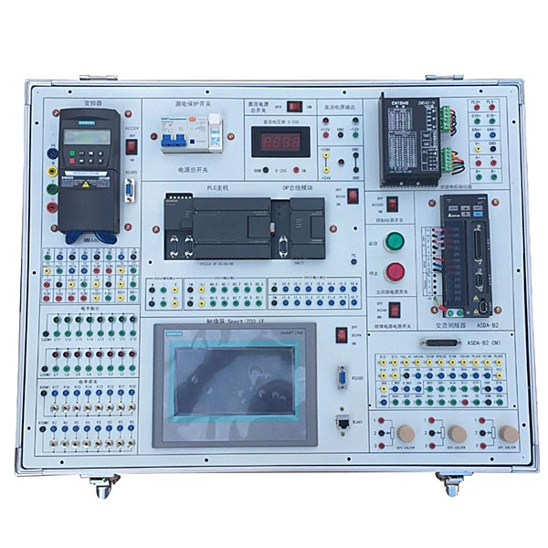


1. Modular design. In the host module, all input and output ports are connected to the experimental board through wires. Each experimental module has independent input, output, and common terminals. Users can easily expand their own modules.
2. The DC motors , relays, and sensors use physical products, which improves the authenticity and practicality of the experiment.
3. Equipped with MCGS industrial control configuration software, it can intuitively carry out basic instruction exercises of PLC , simulation experiments of multiple PLC practical applications and physical experiments. All experiments have configuration bar diagrams for dynamic tracking, and the experimental objects are lifelike and close to industry. Practical application in the field. Through tr*ning with this device, students can quickly adapt to the actual operation in the field.
4. Here students can understand and master the structure and principle of the inverter, the installation of the inverter and the use of the interface terminals, the communication between the inverter and the PC, the communication between the inverter and the touch screen, the setting of the inverter's own parameters, and the inverter's Setting and optimization of motor operating parameters (acceleration, deceleration, speed change, torque control).
When the program debugging is completed, the touch screen can be used alone to control the frequency conversion system. The touch screen provides a graphical human-machine interface, which can change the parameters of the frequency converter and control the operation of the frequency converter.
5. Fieldbus-based configuration monitoring tr*ning teaching: Through the fieldbus network, the tr*ning device (slave station) PLC and the master station PLC conduct 1:N communication. The PLC of the slave station runs the program of the control object. Using the centralized monitoring function of the industrial control network, the master station PLC can monitor any slave station PLC in real time, which meets the requirements of industrial on-site control. Students independently control various tr*ning objects through PLC and perform configuration real-time monitoring (1:1 communication).
2. Technical parameters:
1. Input power supply: three-phase four-wire: ~220V ±10% 50Hz, output power supply 24V, 2A.
2. Working environment: temperature -10℃~+40℃ relative humidity <85% (25℃) Altitude <4000m
3. Safety protection: This experimental device is equipped with a leakage protection switch, which has the function of automatically cutting off the power supply for leakage voltage and leakage current.
4. PLC host: adopts Siemens S7-smart200 series SR30 with 18 input points and 12 output points.
5. Frequency converter host: adopts Siemens V20/0.37KW, equipped with BOP panel.
6. Touch screen: Kunlun Tongt* 7-inch color touch screen
7. 180W three-phase asynchronous motor
8. Virtual simulation system
1. M*ntenance of electricians , electronic motors and vocational qualification tr*ning assessment simulation software
This software is in apk format and can be used on PC or mobile. This software can set faults manually or automatically. This software can manually set fault points through the green box in the circuit diagram (you can set up to 39 fault points), you can also automatically set one random fault point, two random fault points, three random fault points, four random fault points, and five random fault points through the system. It has functions such as toolbox, component library, magnifying glass, circuit diagram, etc. You can choose a multimeter for testing through the toolbox, select appropriate components through the component library, and clearly understand each component and circuit through the magnifying glass. This software allows students to understand the working principle and circuit structure of the motor star-delta start control circuit through the setting of faults in the motor star-delta start control circuit and various investigations.
2. Virtual spectrum analyzer, logic analyzer, oscilloscope, and three-meter simulation software:
This software is in apk format and can be used on PC or mobile terminals. The functions of this software are: resistance measurement, AC voltage measurement (measuring transformer, if the multimeter burns out when measuring the transformer, black smoke will emit prompts and can reset the multimeter), determine the polarity of the transistor, measure the DC voltage (the light turns on when the ammeter is turned on), measure the DC current, and determine the quality of the capacitor. This software can drag the red and black pen tips at will. When the two pen tips are dragged and positioned on the object to be measured, a red circle will be displayed. If the positioning is not accurate, no red circle will be displayed, and when incorrect operations are performed (such as the wrong range selected, If the measured data is wrong, etc.), the meter pointer will be unresponsive, prompting errors and re-measurement, etc. This multimeter can select AC voltage range, DC voltage range, resistance range, current range, resistance adjustment to 0, and can enlarge the display data. Clearly view the measured data size. Students can learn the correct use of multimeters through this software.
3. Microcontroller , PLC programmable design and control virtual simulation software:
This software is developed based on unity3d and has built-in experimental steps, experimental instructions, circuit diagrams, component lists, connection lines, power on, circuit diagrams, scene reset, return and other buttons. After the connections and codes are correct, you can start/stop, The forward movement and reverse movement buttons operate the 3D machine tool model to move. In the connected line state, the 3D machine tool model can be enlarged/reduced and translated.
1. Relay control: Read the experiment instructions and enter the experiment. By reading the circuit diagram, select the relays, thermal relays, switches and other components in the component list and drag and drop them into the electrical cabinet. The limiters are placed in the three-dimensional On the machine tool model, you can choose to cover it, and some component names can be renamed. Then click the Connect Line button to connect terminals to terminals. After successfully connecting the machine tool circuit, choose to turn on the power and proceed. If the component or line An error box will pop up if there is a connection error, and the scene can be reset at any time.
2. PLC control: The experiment is the same as relay control, with the addition of PLC control function. After the connection is completed, enter the program writing interface through the PLC coding button, and write two programs, forward and reverse, with a total of 12 ladder diagram symbols. The writing is completed. Finally, select Submit for program verification. After the verification is successful, turn on the power for operation. Error boxes will pop up for component, line connection, and code errors, and the scene can be reset at any time.
3. Single-chip microcomputer control: The experiment is the same as relay control, with the addition of single-chip microcomputer control function. After the connection is completed, enter the programming interface through the C coding button, enter the correct C language code, and after successful submission and verification, turn on the power for operation, components, lines If there are connection or code errors, an error box will pop up, and the scene can be reset at any time.
3. Experiment content
PLC experiment:
(1) Six types of instruction experiments can be completed:
the first type is basic instruction experiment;
the second type is timer and counter instruction experiment;
the third type is shift register instruction experiment;
the fourth type is set/reset and pulse command experiments;
Category 5 jump command experiments;
Category 6 common function command experiments;
(2) Nine module control experiment projects can be completed:
1. Automatic control of traffic lights;
2. Automatic control of manipulators ;
3 , Control of stage art lights;
4. Control of AC motor Y/Δ starting (the motor simulates rotation through a small DC motor).
5. Automatic control of liquid mixing device (the mixer simulates rotation through a small DC motor).
6. Automatic control of the water level in the water tower;
7. Simulated operation of the four-level conveyor belt;
8. Simulated operation of the m*l sorting system;
9. Assembly line control.
Frequency converter experiment
1. Frequency converter understanding and parameter debugging experiment
2. External control frequency converter Output frequency experiment
3. Analog control inverter output frequency experiment
4. Analog input control motor speed experiment
5. Inverter frequency jump experiment
6. External terminal jog control experiment
7. Inverter stepless speed regulation experiment
8. PID Frequency conversion speed control experiment
9. Speed closed-loop positioning control experiment
Touch screen experiment
1. Installation and use of WINCC fl exible configuration software
2. Basic instruction programming practice experiment
3. Configuration demonstration experiment
4. Configuration variable definition and management experiment
5. Configuration Animation connection experiment
6. User script program experiment
7. Alarm display and alarm data report output experiment
8. Touch screen-based control method experiment
4. Instructions, software and others
|
1 |
"Practical Tr*ning Guide" |
SR30 |
1 copy |
|
|
2 |
PLC user manual |
SR30 |
|
1 set |
|
3 |
Touch screen user manual |
Kunlun Tongt* |
1 set |
|
|
4 |
Inverter User Manual |
V20/0.37kw |
1 set |
|
|
3 |
Programming software |
STEP 7 MicroWIN V4.0 SP9 |
Educational Edition |
1 set |
|
4 |
Configuration Software |
WinCC flexible 2008 |
||
|
5 |
Sample program |
|||
|
6 |
test line |
1 set |
||
|
7 |
Fuse |
Complete equipment configuration |
1 box |
 Wechat scan code follow us

24-hour hotline+86 18916464525

Phone18916464525
ADD:Factory 414, District A, No. 6, Chongnan Road, Songjiang Science and Technology Park, Shanghai ICP: Sitemap