Shanghai Daiyu Education Equipment Manufacturing Co., Ltd.
Language:


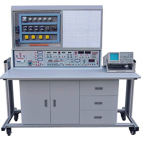


This comprehensive experimental and tr*ning device can not only complete course experiments such as " Electrical Engineering" and "Electrical Principles", but also complete practical tr*ning on courses such as "Electrician Skills Tr*ning", "Electrician Practical Tr*ning" and "Electric Drag Control Circuit and Skills Tr*ning". , and can also expand the experimental tr*ning of PLC programmable control, frequency conversion technology and other courses. The experimental part is completed on the multi-hole universal experimental board, which can complete experimental projects such as AC and DC, oscillation, magnetic circuit circuit, operational amplifier, rectifier circuit, AC and DC amplifier circuit, etc. The practical tr*ning and assessment part is completed on a mesh board, close to the industrial site, with strong hands-on ability and flexible tr*ning methods. It can complete "the use of tools and instruments", "basic electrician skills tr*ning", and "installation, m*ntenance and troubleshooting of electric motors" , "Installation, debugging and m*ntenance of basic motor control circuits", "Fault analysis and treatment of common production machinery electrical control circuits" and other practical tr*ning assessment projects. This device is an ideal product for upgrading existing laboratories in colleges, secondary schools, vocational schools and technical schools or for newly building and expanding laboratories.
2. Features:
1. It can complete electrician experiments and conduct electrician tr*ning and assessment, which greatly saves experimental space and management personnel.
2. The experimental component box is transparent and intuitive. The lid and box body adopt a more scientific press-card structure, which is easy to m*nt*n and disassemble. The component box is arbitrarily plugged into the experimental circuit on the multi-hole universal experimental board, and the method is flexible, allowing students to flexibly apply and quickly master the knowledge they have learned.
3. The practical tr*ning part is completed on the mesh board, which is easy to operate, flexible and easy to replace. It is close to the industrial site and easy to expand the tr*ning function or launch new tr*ning projects.
4. There are rich experimental tr*ning projects and complete functions of the equipment.
5. It is equipped with a voltage-type current-type leakage protector, and a single- chip microcomputer automatic full-process monitoring device for overload or short circuit. Once it occurs, the power supply can be automatically cut off, and the working power supply can be restarted only after the fault is eliminated. Can ensure the safety of equipment and operators.
3. Technical performance:
1. Working power supply: three-phase four-wire (or three-phase five-wire) ~ 380V ±5% 50Hz
2. Temperature: -10℃~40℃, relative humidity <85% (25℃)
3. Device capacity: <1KVA
4. Weight: 200Kg
4. Functional composition
1. Power supply and parameters:
1.1 Input power supply: three-phase four-wire power supply, the signal light is on during input
1.2 Power output: After the m*n power is turned on, press the start button, the three-phase four-wire AC power output will be output, and a 450V AC voltmeter will indicate the output voltage. There are 0/1 switches to individually control the output of the three-phase power supply.
1.3 Adjustable AC and DC power supply: 0~240V continuously adjustable AC power output, indicated by a meter. The maximum output current is 2A, and there is also a 0-250V DC power output (equipped with a 0.5KVA single-phase voltage regulator)
1.4 Dual-channel constant-current voltage-stabilized power supply: It has overload and short-circuit protection functions, the output voltage of both channels is 0-30V, the built-in relay automatically shifts gears, and the multi-turn potentiometer is continuously adjusted, making it easy to use. The maximum output current is 2A, with current value preset function. Voltage stability <10-2, load stability <10-2, ripple voltage <5mv.
1.5 DC regulated power supply: fixed +5V, current 0.5A.
1.6 Low-voltage AC power supply: output 2V, 4V, 6V, 8V, 10V, 12V, 14V, 16V, 18V, 20V, 24V power supply, maximum current 1.5A.
2. Safety protection: It is equipped with voltage-type and current-type leakage protectors, and has a single-chip microcomputer to automatically control the entire monitoring device. Overload or short circuit will automatically cut off the m*n power supply. After troubleshooting, press the reset button to restart the power supply to ensure that the operator and the equipment Safety.
3. Function signal generator (sine wave, triangle wave, rectangular wave)
3.1 Frequency range: 5Hz to 550KHz, divided into five frequency bands.
3.2 Frequency indication: read directly from the Hz meter.
3.3 Voltage output range: sine wave 5Hz-250KHz>4.5V, 250KHz-550KHz>3.5Hz
Three levels of attenuation: 0db, 20db, 40db, with continuous fine adjustment
Rectangular wave: 5Hz-250KHz>4.5V, 250KHz-550KHz>3.5Hz, amplitude continuously adjustable
Triangular wave: 5Hz-250KHz>1V
4. A DC digital display mA meter, measuring range: 0-2000mA.
5. An intelligent true RMS AC ammeter: measuring range 0~5A.
6. Intelligent power and power factor meter: The measurement accuracy is level 1.0, the power factor measurement range is 0.3-1.0, and the voltage and current range is 450V and 5A.
5. Composition and equipment of the whole room
1. The experimental tr*ning screen is made of iron double-layer matte spray plastic, with the left side being a mesh board and the right side being a porous universal experimental board. The lower part is the power supply, signal and control unit.
2. Operation table: aluminum wood structure, the desktop is made of fireproof, waterproof, wear-resistant high-density board. One table with two seats. The lower part of the table is a component storage cabinet for placing components.
3. Simulation system
1. Electricity safety and electric shock first *d virtual simulation system (demo and copyright certificate provided): The software uses a virtual screen that combines two-dimensional and three-dimensional to teach students the safety of electricity and first *d methods. The software has single-phase electric shock, two-phase electric shock, and two-phase electric shock first *d. Principles of electric shock, step-over electric shock, low voltage electric shock first *d, high voltage electric shock first *d, artificial respiration rescue method, holding hands breathing rescue method, chest heart compression rescue method, etc., single-phase electric shock rep*r live disconnection, rep*r socket electric shock, outdoor Demonstration of principles such as electric shock. The teaching of low-voltage electric shock and high-voltage electric shock m*nly expl*ns and demonstrates to students how to rescue people who are suffering from low-voltage electric shock or high-voltage electric shock. Artificial respiration rescue method, hand-holding breathing rescue method, and chest cardiac compression rescue method are demonstrated using 3D virtual simulation technology. After rendering and Polish it to make the model look like the real part and look realistic. Through practical tr*ning, students can be educated on the safe use of electricity in the tr*ning room, improve students' safety awareness, and enable students to learn some self-rescue methods, so that students can take cert*n safety measures to protect themselves when encountering danger, and become familiar with various Causes of electrical accidents and practical measures to deal with them to reduce the occurrence of electrical accidents.
2. M*ntenance of electricians, electronic motors and vocational qualification tr*ning assessment simulation software (providing demonstration and copyright certificate): The software content includes common sense of safe electricity use, electrician tools, electrician diagrams, electrician instruments, electrician lighting circuits, motors, transformers, low-voltage electrical appliances, Electric mops, oscilloscopes, low-frequency signal sources, welding processes, SMT technology, electronic product manufacturing processes, troubleshooting, wiring, three-dimensional disassembly and assembly of reducers, disassembly and assembly of shafting mechanisms (including cylindrical gear shafting, bevel gear shafting, worm shaft Department and more than ten experiments) and other modules, schools can select corresponding tr*ning modules for tr*ning according to students' learning progress.
3. Three-meter simulation software (demo and copyright certificate provided): This software is in apk format and can be used on PC or mobile terminals. The functions of this software are: measurement of resistance and measurement of AC voltage ( Measuring the transformer, if the multimeter burns out when measuring the transformer, black smoke will appear and the multimeter can be reset), transistor polarity judgment, DC voltage measurement (the light will turn on when the ammeter is turned on), DC current measurement, and capacitance is good. Bad judgment. This software can drag the red and black pen tips at will. When the two pen tips are dragged and positioned on the object to be measured, a red circle will be displayed. If the positioning is not accurate, no red circle will be displayed, and when incorrect operations are performed (such as the wrong range selected, If the measured data is wrong, etc.), the meter pointer will be unresponsive, prompting errors and re-measurement, etc. This multimeter can select AC voltage range, DC voltage range, resistance range, current range, resistance adjustment to 0, and can enlarge the display data. Clearly view the measured data size. Students can learn the correct use of multimeters through this software.
4. Teacher teaching design system (provides demonstration and copyright certificate): This system is in apk format and can be used on PC or mobile. This system can set faults manually or automatically. This system has passed The green box in the circuit diagram selects manual setting of fault points (up to 39 fault points can be set), or the system can automatically set one random fault point, two random fault points, three random fault points, and four random fault points automatically. Fault point setting, five random fault point settings. This system has toolbox, component library, magnifying glass, circuit diagram and other functions. You can choose a multimeter for detection through the toolbox, select appropriate components through the component library, and you can clearly see the results through the magnifying glass. Understand the various components and circuits. This system allows students to understand the working principle and circuit structure of the motor star-delta start control circuit through the setting of faults in the motor star-delta start control circuit and various investigations.
6. Reference experimental tr*ning projects
A: Practical tr*ning part
1. Use of low-voltage electroscope pen
2. Use and identification of commonly used tools
3. Connection of common wires and restoration of insulation
4. Soldering iron disassembly and soldering skills tr*ning
5. Electrician diagram reading tr*ning
6. Electrical wiring process
7. Installation wiring of fluorescent lamp circuit
8. Single-phase watt-hour meter direct wiring circuit installation
9. Single-phase electricity meter is installed through the wiring circuit of the current transformer
10. Distribution board installation
11. indoor wiring
12. Indoor lighting circuit installation
13. Use and reading of multimeter transfer switch
14. Measurement of AC voltage
15. Measurement of DC voltage and DC current
16. Installation of ammeter and voltmeter
17. Measurement of resistance
18. The use of megger, clamp ammeter and ground resistance measuring instrument
19. Measurement of single-phase power and power factor
20. Installation and wiring of three-phase four-wire active energy meter
twenty one. Installation and wiring of three-phase four-wire active energy meter via current transformer
twenty two. Disassembly and assembly of commonly used switch relays
twenty three. Disassembly and assembly of AC contactor
twenty four. Structural observation and detection of commonly used starters
25. Manufacturing of small transformers
26. Small transformer fault inspection and troubleshooting
27. Disassembly, assembly and testing of three-phase squirrel cage motors
28. Three-phase squirrel cage asynchronous motor operation inspection
29. Periodic m*ntenance of three-phase squirrel cage asynchronous motor
30. Fault analysis of three-phase squirrel cage motor
31. Troubleshooting of local faults in stator winding
32. Disassembly and assembly of single-phase capacitor motor windings
33. Single-phase capacitor motor faults and troubleshooting
34. Installation and m*ntenance tr*ning of manual forward control circuit
35. Contactor inching forward control
36. Forward rotation control with self-locking
37. Forward rotation control with overload protection
38. Contactor interlocking forward and reverse control
39. Button interlocking forward and reverse control circuit
40. Button and contactor composite interlocking control circuit
41. Touch switch control Y-△ step-down control
42. Interlock control of X62-W milling machine spindle and feed motor
43. Time relay control Y-△ step-down starting control
44. Simulation installation of C620-1 lathe control circuit
B: Experimental part
1. Use of electrical measuring instruments
2. Identification and detection of commonly used components
3. Volt-ampere characteristics of linear components and nonlinear components
4. External characteristics of power supply
5. Measurement of potential value and voltage value
6. Range extension for ammeters and voltmeters
7. Verification of Kirchhoff's Laws
8. Verification of Lenz's law
9. Verification of the superposition principle and reciprocity theorem
10. Verification of Thevenin's Theorem and Norton's Theorem
11. Equivalent transformation of voltage source and current source
12. Research on controlled source characteristics
13. First order circuit experiment
14. Transition process of second-order circuit
15. Study the characteristics of LC components in DC and AC circuits
16. Conditions for the load to obt*n maximum power
17. Measurement of AC circuit parameters
18. Characteristics of RLC components in sinusoidal AC circuits
19. RL and RC series circuit experiments
20. RLC series resonant circuit
twenty one. Fluorescent lamp circuit connection and power factor improvement
twenty two. Star and delta connection of three-phase load
twenty three. Three-phase circuit and power measurement
twenty four. Research on RC Frequency Selective Network
25. Two-port network research
26. Single phase transformer experiment
27. Mutual inductance circuit experiment
28. Use and starting of three-phase asynchronous motor
29. Basic circuit of three-phase motor relay contact control
30. Three-phase motor Y-△ starting control experiment
31. Sequential control experiment of three-phase motor
32. Three-phase motor energy consumption braking control experiment
33. The simplest circuit
34. Selection of potentials and reference points at each point in the circuit
35. series connection of resistors
36. Resistors in parallel
37. Mixed connection of resistors
38. resistor divider circuit
39. Ohm's law for the whole circuit
40. Bridge application and balancing conditions
41. node voltage method
42. loop voltage method
43. branch current method
44. RCL parallel circuit
45. series circuit
46. Transformer structure and working principle
47. Kirchhoff's first law
48. Kirchhoff's second law
49. Fluorescent lamp circuit principle
50. Expand the voltmeter range
51. Expand ammeter range
52. Transition process of RC circuit
53. RL transition process
54. series circuit of capacitors
55. capacitor parallel circuit
56. Capacitor charging and discharging
57. The role of capacitors in AC and DC
58. Movement of bar magnet in coil
59. Mixed connection of capacitors
60. Pure resistance, inductance, capacitance circuits
61. Magnetic coupling coil sequence
62. Counter-series of magnetically coupled coils
63. How an ohmmeter works
64. Double switch two ground control
65. Use an oscilloscope to observe the hysteresis loop
66. Magnetic Circuit Ohm's Law
67. The mutual inductance of the two coils and the same terminal
68. mutual inductance coupling
69. How to improve power factor
70. Measurement of single-phase circuit power
71. Radio recorder power circuit
72. filter circuit
73. The relationship between resistance and temperature: Use voltammetry to measure the resistance of the filament at different voltages.
74. Three-phase asynchronous motor knife control forward rotation experiment
75. Control circuit with overload protection
76. Button controlled forward and reverse control circuit
77. Contactor control star-delta step-down starting control circuit
7. Equipment and equipment:
|
serial number |
name |
Quantity per unit |
unit |
Remark |
|
1. |
Electrical tools such as test leads, wrenches, needle nose pliers, wire cutters, wire strippers, etc. |
1 |
set |
|
|
2. |
Soldering iron and soldering iron stand |
1 |
set |
|
|
3. |
Analog multimeter MF-50 |
1 |
Only |
|
|
4. |
Digital multimeter 890B+ |
1 |
Only |
|
|
5. |
Single phase electricity meter |
1 |
Only |
|
|
6. |
Three-phase electricity meter |
1 |
Only |
|
|
7. |
Current Transformer |
3 |
Only |
|
|
8. |
Megger |
1 |
Only |
|
|
9. |
clamp ammeter |
1 |
Only |
|
|
10. |
fuse box |
3 |
Only |
|
|
11. |
fuse |
6 |
Only |
|
|
12. |
Switches, garden sockets, flat lamp holders |
2 each |
Only |
|
|
13. |
20W fluorescent lamp |
1 |
set |
|
|
14. |
Phase commutation switch |
1 |
Only |
|
|
15. |
Resistors and transformer components |
1 |
set |
|
|
16. |
Hacksaw frame |
1 |
Bundle |
|
|
17. |
single phase motor |
1 |
tower |
|
|
18. |
Three-phase motor 180W |
2 |
tower |
|
|
19. |
AC contactor |
4 |
Only |
|
|
20. |
Combination Switch |
1 |
Only |
|
|
twenty one. |
3H iron shell button |
1 |
Only |
|
|
twenty two. |
thermal relay |
2 |
Only |
|
|
twenty three. |
Time Relay |
1 |
Only |
|
|
twenty four. |
50W transformer |
1 |
Only |
|
|
25. |
single pole switch |
1 |
Only |
|
|
26. |
Three-phase knife |
1 |
Only |
|
|
27. |
signal light |
1 |
Only |
|
|
28. |
Electric socket |
3 |
Only |
|
|
29. |
AC and DC ammeter |
6 |
Only |
|
|
30. |
Resistors, potentiometers, inductors, capacitors, transformers, bar magnets and other components required for the experiment |
1 |
set |
Components are installed in transparent unit boxes |
|
31. |
Wire duct |
2 |
rice |
|
|
32. |
Student stool |
2 |
open |
Note: If the parts factory stops production or is out of stock, parts of equal or higher performance will be used instead.
 Wechat scan code follow us

24-hour hotline+86 18916464525

Phone18916464525
ADD:Factory 414, District A, No. 6, Chongnan Road, Songjiang Science and Technology Park, Shanghai ICP: Sitemap