Shanghai Daiyu Education Equipment Manufacturing Co., Ltd.
Language:


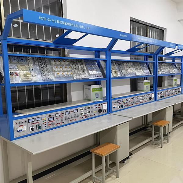


This device is a highly simulated electronic welding assembly operating platform that meets the comprehensive, design and innovative tr*ning requirements for students in electronic production, electronic design competitions, course design, graduation projects, innovative practice activities, etc. It can cultivate students’ practical ability and innovation ability. It is suitable for teaching practice and appr*sal assessment of courses related to electronics majors such as technical schools, vocational tr*ning schools, vocational education centers, appr*sal stations/institutes, etc.
2. Technical performance
1. Input power: three-phase four-wire 380V±10% 50Hz
2. Working environment: temperature -10℃~+40℃, relative humidity <85% (25℃)
3. Device capacity: <200VA
3. Practical tr*ning equipment
It m*nly consists of a tr*ning platform , power cabinet, tr*ning circuit board, component package, tool kit, etc.
1. Tr*ning platform
The tr*ning platform is m*nly composed of a tr*ning table, a tr*ning panel, a steel-wood frame, a top frame, etc.
(1) Equipped with a tool cabinet where tr*ning kits, tools and materials can be placed; the table is paved with green anti-static table mats; there are also four universal wheels with brakes for easy movement and fixation.
(2) There is an electric fan and a 30W fluorescent lamp (lighting equipment) on the top frame.
2. Console
1. Three phase fuse
3. Three-phase power input indicators
4. M*n switch: m*n switch of the power supply of the experimental bench , with leakage and overload protection
5. Test button: Test the leakage function of the leakage switch
6. Power input indicator 1
7. 3 power output indicators (red, green and yellow)
8. AC voltmeter: Indicates output line voltage
9. Voltage conversion switch: Used in conjunction with a voltmeter to monitor the size and symmetry of the output line voltage
10. 5 terminal blocks: unit A three-phase four-wire and ground wire output
11. Ammeter W phase current output indication
12. O/I switch: three-phase four-wire power output control
(Improve safety factor)
13. 2 terminal blocks: Unit B AC low-voltage power output
14. Electric meter (2A): Unit B AC current indication
15. Knob: Unit B 3-24V AC low voltage selection output
16. Switch: C unit dual-channel DC regulated power supply switch
17. Knob: C unit dual-channel I channel steady flow adjustment
18. Knob: C unit dual-channel II channel steady flow adjustment
19. 2 terminal blocks: Unit C Ⅰ DC regulated output
20. Insurance holder: C unit dual-channel regulated power supply fuse
twenty one. 4 electric meters: dual-channel regulated power supply voltage and current indication
twenty two. Terminal block: D unit DC 5V regulated output
twenty three. Electric meter: D unit current 0.5V output indication
twenty four. Switch 1: Controls various low-voltage alternating current and signal sources
25. Switch 2: Control the AC and DC voltage-regulated power supply of unit E
26. Electric meter: E unit AC voltage output indication
27. 4 terminal blocks: E unit AC and DC output ports
28. Knob: E unit 0~240V voltage adjustment
29. Socket: G unit 220V output socket
30. Knob: Audio power amplifier volume adjustment
31. 2 terminal blocks: audio signal input
32. Button: Single pulse enable switch
33. 3 terminal blocks: single pulse output port
34. Electric meter: function generator sine wave output voltage indication
35. Knob: coarse adjustment of three-level attenuation amplitude of sine wave output
36. Knob: Sine wave output port
37. Terminal block: sine wave output port
38. Knob: Rectangular wave output amplitude adjustment
39. Terminal block: triangle wave output port
40. Knob: Function signal generator frequency fine adjustment
41. Terminal block: rectangular wave output port
42. Knob: Function signal generator five-level frequency coarse adjustment
43. Electric meter: function generator output frequency indication
44. Multimeter: digital
47. Universal circuit board: specification 35×90cm, component boxes can be assembled and inserted on it for experiments
3. Practical tr*ning circuit board (2 sets/unit)
Regularly equipped with six-tube superheterodyne FM radio, LED digital electronic clock, multi-channel answering machine and other tr*ning circuit boards.
4. Practical tr*ning tool kit
Equipped with commonly used digital multimeter, component box, wire strippers, needle nose pliers, diagonal pliers, small Phillips screwdriver, large Phillips screwdriver, small slotted screwdriver, large slotted screwdriver, small tweezers, scissors, vacuum pen, electric Soldering iron, magnifying glass lamp, soldering iron stand, soldering wire, solder absorber and other tools.
5. Simulation system
1. Electricity safety and electric shock first *d virtual simulation system (demo and copyright certificate provided): The software uses a virtual screen that combines two-dimensional and three-dimensional to teach students the safety of electricity and first *d methods. The software has single-phase electric shock, two-phase electric shock, and two-phase electric shock first *d. Principles of electric shock, step-over electric shock, low voltage electric shock first *d, high voltage electric shock first *d, artificial respiration rescue method, holding hands breathing rescue method, chest heart compression rescue method, etc., single-phase electric shock rep*r live disconnection, rep*r socket electric shock, outdoor Demonstration of principles such as electric shock. The teaching of low-voltage electric shock and high-voltage electric shock m*nly expl*ns and demonstrates to students how to rescue people who are suffering from low-voltage electric shock or high-voltage electric shock. Artificial respiration rescue method, hand-holding breathing rescue method, and chest cardiac compression rescue method are demonstrated using 3D virtual simulation technology. After rendering and Polish it to make the model look like the real part and look realistic. Through practical tr*ning, students can be educated on the safe use of electricity in the tr*ning room, improve students' safety awareness, and enable students to learn some self-rescue methods, so that students can take cert*n safety measures to protect themselves when encountering danger, and become familiar with various Causes of electrical accidents and practical measures to deal with them to reduce the occurrence of electrical accidents.
2. M*ntenance of electricians, electronic motors and vocational qualification tr*ning assessment simulation software (providing demonstration and copyright certificate): The software content includes common sense of safe electricity use, electrician tools, electrician diagrams, electrician instruments, electrician lighting circuits, motors, transformers, low-voltage electrical appliances, Electric mops, oscilloscopes, low-frequency signal sources, welding processes, SMT technology, electronic product manufacturing processes, troubleshooting, wiring, three-dimensional disassembly and assembly of reducers, disassembly and assembly of shafting mechanisms (including cylindrical gear shafting, bevel gear shafting, worm shaft Department and more than ten experiments) and other modules, schools can select corresponding tr*ning modules for tr*ning according to students' learning progress.
3. Three-meter simulation software (demo and copyright certificate provided): This software is in apk format and can be used on PC or mobile terminals. The functions of this software are: measurement of resistance and measurement of AC voltage ( Measuring the transformer, if the multimeter burns out when measuring the transformer, black smoke will appear and the multimeter can be reset), transistor polarity judgment, DC voltage measurement (the light will turn on when the ammeter is turned on), DC current measurement, and capacitance is good. Bad judgment. This software can drag the red and black pen tips at will. When the two pen tips are dragged and positioned on the object to be measured, a red circle will be displayed. If the positioning is not accurate, no red circle will be displayed, and when incorrect operations are performed (such as the wrong range selected, If the measured data is wrong, etc.), the meter pointer will be unresponsive, prompting errors and re-measurement, etc. This multimeter can select AC voltage range, DC voltage range, resistance range, current range, resistance adjustment to 0, and can enlarge the display data. Clearly view the measured data size. Students can learn the correct use of multimeters through this software.
4. Teacher teaching design system (provides demonstration and copyright certificate): This system is in apk format and can be used on PC or mobile. This system can set faults manually or automatically. This system has passed The green box in the circuit diagram selects manual setting of fault points (up to 39 fault points can be set), or the system can automatically set one random fault point, two random fault points, three random fault points, and four random fault points automatically. Fault point setting, five random fault point settings. This system has toolbox, component library, magnifying glass, circuit diagram and other functions. You can choose a multimeter for detection through the toolbox, select appropriate components through the component library, and you can clearly see the results through the magnifying glass. Understand the various components and circuits. This system allows students to understand the working principle and circuit structure of the motor star-delta start control circuit through the setting of faults in the motor star-delta start control circuit and various investigations.
5. Practical tr*ning projects
Task 1: Production of multi-channel answering machines
1) Understanding and measuring components of multi-channel answering machines
2) Reading multi-channel transponder schematic diagram and filling in process documents
3) Multi-channel answering machine assembly tools and preparation process
4) Multi-channel answering machine motherboard welding
5) Multi-channel answering machine motherboard debugging
6) Multi-channel responder circuit board inspection
Task 2: LED digital electronic clock production
1) Understanding and measuring LED digital electronic clock components
2) Reading of LED digital electronic clock schematic diagram and filling in process documents
3) Assembly tools and preparation process of LED digital electronic clock
4) LED digital electronic clock motherboard welding
5) LED digital electronic clock m*nboard debugging
6)LED digital electronic clock motherboard inspection
Task 3: Complete production of six-tube superheterodyne FM radio
1) Understanding and measuring FM radio components
2) Reading FM radio schematic diagram and filling in process documents
3) Common assembly tools and preparation processes for FM radios
4) Six-tube superheterodyne FM radio m*nboard welding
5) Debugging of the six-tube superheterodyne FM radio
6) Complete inspection of six-tube superheterodyne FM radio
7) Six-tube superheterodyne FM radio package
|
serial number |
name |
quantity |
|
1. |
Tr*ning platform |
1 |
|
2. |
console |
1 |
|
3. |
Tr*ning circuit board |
2 |
|
4. |
Practical tr*ning tool kit |
1 |
|
5. |
Tr*ning instructions |
1 |
|
6. |
stool |
2 |
Electronic basic component box set
It is equipped with a universal porous circuit board, on which components can be randomly inserted into the experimental circuit to form an experimental circuit.
The experimental component box configuration is as follows:
|
Component name |
model |
quantity |
Remark |
|
resistance |
0.5Ω |
1 |
1/2W |
|
resistance |
1Ω |
1 |
1/2W |
|
resistance |
5.1Ω |
2 |
1/2W |
|
resistance |
51Ω |
1 |
1/2W |
|
resistance |
100Ω |
3 |
1/4W |
|
resistance |
150Ω |
1 |
1/4W |
|
resistance |
200Ω |
1 |
1/4W |
|
resistance |
300Ω |
2 |
1/4W |
|
resistance |
330Ω |
2 |
1/4W |
|
resistance |
430Ω |
1 |
1/4W |
|
resistance |
470Ω |
1 |
1/4W |
|
resistance |
510Ω |
2 |
1/4W |
|
resistance |
680Ω |
2 |
1/4W |
|
resistance |
820Ω |
2 |
1/4W |
|
resistance |
1K |
3 |
1/4W |
|
resistance |
1.5K |
1 |
1/4W |
|
resistance |
2K |
2 |
1/4W |
|
resistance |
2.4K |
2 |
1/4W |
|
resistance |
2.7K |
1 |
1/4W |
|
resistance |
3.3K |
3 |
1/4W |
|
resistance |
3.9K |
1 |
1/4W |
|
resistance |
4.7K |
1 |
1/4W |
|
resistance |
5.1K |
1 |
1/4W |
|
resistance |
6.8K |
2 |
1/4W |
|
resistance |
10K |
4 |
1/4W |
|
resistance |
13K |
1 |
1/4W |
|
resistance |
20K |
2 |
1/4W |
|
resistance |
39K |
2 |
1/4W |
|
resistance |
51K |
1 |
1/4W |
|
resistance |
100K |
2 |
1/4W |
|
resistance |
200K |
1 |
1/4W |
|
resistance |
1M |
1 |
1/4W |
|
resistance |
10M |
1 |
1/4W |
|
Potentiometer |
470Ω |
1 |
1/2W |
|
Potentiometer |
1K |
2 |
1/2W |
|
Potentiometer |
4.7K |
1 |
1/2W |
|
Potentiometer |
10K |
1 |
1/2W |
|
Potentiometer |
22K |
1 |
1/2W |
|
Potentiometer |
100K |
1 |
1/2W |
|
Potentiometer |
470K |
2 |
1/2W |
|
electrolytic capacitor |
1UF |
1 |
16V |
|
electrolytic capacitor |
10UF |
3 |
16V |
|
electrolytic capacitor |
47UF |
3 |
16V |
|
electrolytic capacitor |
220UF |
1 |
35V |
|
electrolytic capacitor |
470UF |
1 |
35V |
|
ceramic capacitor |
300P |
1 |
63V |
|
ceramic capacitor |
1000P |
2 |
63V |
|
ceramic capacitor |
0.01UF |
3 |
63V |
|
ceramic capacitor |
0.1UF |
1 |
63V |
|
ceramic capacitor |
0.47UF |
1 |
63V |
|
ceramic capacitor |
2UF |
1 |
250V |
|
audio input transformer |
1 |
||
|
audio output transformer |
1 |
||
|
transformer |
220/6V.6V.24V |
1 |
8W |
|
Inductor |
8Ω |
1 |
|
|
Inductor |
390UH |
1 |
|
|
Electric device) |
8W |
1 |
|
|
diode |
4007 |
4 |
|
|
diode |
2AP9 |
1 |
|
|
led |
2 |
||
|
Zener diode |
2CW54 |
1 |
|
|
Zener diode |
2CW76 |
1 |
|
|
crystal oscillator |
10M |
1 |
|
|
field effect transistor |
3DJ6 |
1 |
|
|
Single knot tube |
BT33 |
1 |
|
|
Thyristor |
KP1 |
2 |
|
|
triode |
3DG6 |
2 |
|
|
triode |
3DG12 |
1 |
|
|
triode |
3AX31 |
2 |
|
|
triode |
3DA1 |
1 |
|
|
Three-terminal voltage stabilization |
7805 |
1 |
|
|
Indicator light (signal light) |
6V 0.1A |
1 |
|
|
switch |
4 |
||
|
trumpet |
1 |
||
|
relay |
6V |
1 |
|
|
music integration |
4V |
1 |
|
|
Level switch and logic level indication |
1 |
||
|
Light bulb |
220V/15W |
12 |
Prepare yourself |
|
lamp holder |
12 |
||
|
bar magnet |
1 |
||
|
Primary and secondary coils |
1 |
||
|
DC meter |
5MA |
1 |
|
|
DC meter |
10MA |
1 |
|
|
DC meter |
50MA |
3 |
|
|
DC meter |
200MA |
1 |
|
|
DC meter |
1V |
1 |
|
|
DC meter |
15V |
1 |
|
|
DC meter |
±100UA |
1 |
|
|
AC meter |
500MA |
3 |
|
|
fluorescent tube |
8W |
1 |
|
|
Fluorescent lamp holder |
2 |
||
|
Starter |
1 |
||
|
Integrated seat |
14 feet |
2 |
|
|
Integrated seat |
16 feet |
1 |
|
|
Integrated op amp |
UA741 |
2 |
|
|
timer |
NE555 |
1 |
|
|
TTL NAND gate |
74LS00 |
1 |
|
|
TTL NOT gate |
74LS04 |
1 |
|
|
TTL AND gate |
74LS08 |
1 |
|
|
TTL NAND gate |
74LS20 |
1 |
|
|
TTL OR gate |
74LS32 |
1 |
|
|
decoder |
74LS42 |
1 |
|
|
TTL flip-flop |
74LS74 |
1 |
|
|
seven-segment decoder |
74LS247 |
1 |
|
|
full adder |
74LS283 |
1 |
|
|
CMOS NOR gate |
CD4002 |
1 |
|
|
Digital Tube |
546R |
1 |
|
|
AC contactor |
CJ10﹣10A 380V |
5 |
 Wechat scan code follow us

24-hour hotline+86 18916464525

Phone18916464525
ADD:Factory 414, District A, No. 6, Chongnan Road, Songjiang Science and Technology Park, Shanghai ICP: Sitemap