Shanghai Daiyu Education Equipment Manufacturing Co., Ltd.
Language:


This device is developed in accordance with the "Programmable Control System Designer" tr*ning and the national occupational standard assessment syllabus formulated by the Ministry of Human Resources and Social Security, with appropriate additions of new technologies, and in accordance with the requirements of vocational education and tr*ning, vocational skills appr*sal and practical tr*ning teaching of. It is suitable for vocational colleges, vocational tr*ning schools, vocational education centers, appr*sal stations/institutes to carry out tr*ning and skill appr*sal for fourth, third and second level programmable control system designers.
2. R&D background
1. This device is based on the "Programmable Control System Designer" tr*ning and the national occupational standard assessment syllabus formulated by the Ministry of Human Resources and Social Security, with appropriate additions of new technologies, and in accordance with the requirements of vocational education and tr*ning, vocational skills appr*sal and practical tr*ning teaching And developed.
2. With the rapid development of industry, processor requirements are constantly increasing, and teaching needs to keep pace with the times. Equipment must be continuously upgraded, and teaching needs to start from the basics. At the same time, to meet the needs, duplication of laboratory construction will lead to a waste of money and laboratory space.
3. A product requires multiple processing techniques, resulting in complex industrial field equipment. One host cannot complete all the work, and multiple sites need to cooperate with each other to complete the work.
4. Assessments at different levels require different equipment and cannot be combined organically. Some practical tr*ning cannot be considered to check students’ acceptance after completion.
3. Product Features
1. The construction concept of practical tr*ning is one-time construction. This equipment adopts a universal wide expansion port. All the I/O ports of the host can be led out through the expansion port. It can be used for plug-in tr*ning and wire-connected practical operations. tr*ning; there are also two removable mesh boards to assess students at different levels.
2. In terms of host selection, from the small FX3U series PLC to the medium FX5U series PLC to the large Q series PLC, it fully covers Mitsubishi’s commonly used PLC types. The host can be connected to the tr*ning area through the parallel port for practical tr*ning. From the basic small PLC Starting from the beginning, then to medium-sized PIC, and finally to large-scale PLC, the learning concept from simple to complex makes it easier for students to accept and learn more conveniently.
3. It adopts a modular modular structure, including switching values, analog values, frequency conversion speed regulation, touch screen, communication modules, etc., and is equipped with MCGS industrial control configuration monitoring software to realize simulation and information-based practical tr*ning and teaching.
4. Project tr*ning module: Use current typical programmable controllers and bus technologies to complete the control of logic, simulation, process, motion, etc. in simulated objects and physical models of typical cases in industrial production.
5. Simulation tr*ning and teaching: The PLC operating status is displayed in real time through the virtual environment, simulating industrial on-site control, and can carry out programming tr*ning, program writing testing and other functions.
6. Modular network system: The network structure is m*nly composed of Mitsubishi hosts Q03UDV, FX5U-32MT, and FX3U-32MT. An industrial network is constructed based on the application history of Mitsubishi PLC in industry. Network communication involves CCLINK communication and Mitsubishi inverter special protocols. Multi-layer network communication such as slave communication and Ethernet communication.
4. Technical performance
1. Input power supply: three-phase four-wire (or three-phase five-wire) AC380V±10% 50Hz
2. Device capacity: <0.5kVA
3. Weight: 100kg
4. Overall dimensions: 1310mm×700mm×1780mm
5. Safety protection: It has leakage voltage and leakage current protection devices, and is safe and in line with national standards.
6. Virtual multimeter parameters:
AC voltage ranges: 10, 50, 250, 1000
DC voltage range points: 0.25, 1, 2.5, 10, 50, 250, 1000
Ohm scale: x1, x10, 100, 1000, 1K, x10K, x100K
Ammeter gears: 50μa, 0.5, 5, 50, 500
BATT: 1.2-3.6V, RL=12Ω
BUZZ:R×3
Infrared emission detection function: vertical angle ±15°, distance 1-30cm
Transistor measuring hole
5. Basic configuration and functions
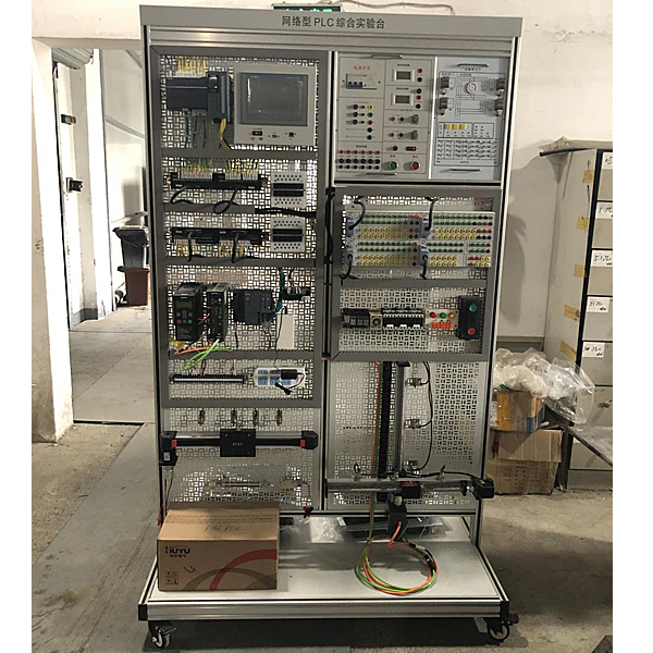
The tr*ning device consists of a tr*ning platform, power module, PLC simulation control module, Q03UDV, FX5U-32MT, FX3U-32MT, frequency conversion speed regulation unit, touch screen unit, Ethernet switch, two-dimensional control unit, basic electrician tr*ning unit, AC It is composed of motor , profile computer desk and experimental wires. The relevant electrical component interfaces are drawn out through multi-functional terminals, with two methods: jack-type experimental verification and wiring-type engineering tr*ning. Students can independently build relevant electrical control circuits.
1. Practical tr*ning platform
The platform adopts a vertical mesh plate structure, which is made of industrial aluminum profiles. The mesh plate on the left is a fixed structure; on the right are two detachable mesh plates. There are universal wheels with brakes at the bottom for easy movement. The layout and shape are beautiful and elegant.
2. Power module
Provides three-phase 380V AC power supply and single-phase 220V AC power supply. The AC power output is equipped with an intelligent equipment control and safety protection system, which can automatically protect ag*nst overcurrent and direct short circuit between phases and lines. And provide DC 24V/5A power supply.
3. PLC simulation control module
After students write the control program in the standard PLC programming environment, they compile and download it to the PLC for practical tr*ning to achieve real-time control of the virtual scene. The hanging box focuses on learning PLC application simulation control programming tr*ning, and uses a pistol plug-in sheath structure tr*ning connection line to build a tr*ning circuit.
It can complete digital display control, answering machine control, sky tower light control, musical fount*n control, intersection traffic light control, water tower water level control, automatic feeding and loading system control, four-section conveyor belt control, assembly line control, and various liquid mixing Practical tr*ning projects include device control, automatic forming machine control, automatic rolling mill control, m*l sorting machine control, vending machine control, robot control, three-story elevator control, machining center control, automatic washing machine, electroplating production line, etc.
4. Mitsubishi Q03 unit ( or Siemens 1500 unit)
Mitsubishi Q03 unit : Stored program repeated operation [input and output control method] Refresh method (when direct access method input and output (DX□, DY□) is specified, direct access method input and output can be performed) [Programming language (sequence program control) Language)] Relay symbol language, logic symbol language, MELSAP3 (SFC), MELSAP-L, function block, structured text (ST) [Processing speed (sequence program instructions)] LD X0 1.9ns; MOV D0 D1 3.9ns[ Constant scan (function used to keep scan time constant)] 0.5~2000ms (can be set in 0.1ms increments) (according to parameter settings) [Program capacity] 30K steps (120K bytes) [Memory capacity] . Program memory ( Drive 0): 120K bytes. Memory card (SD) (Drive 2): Installable SD memory card (SD/SDHC) capacity (max. 32G bytes). Standard RAM (Drive 3) When the extended SRAM cartridge is not used: 192K bytes when using the extended SRAM cartridge: the capacity when the extended SRAM cartridge is not used + the capacity of the extended SRAM cartridge (maximum of the extended SRAM cartridge is 8M bytes). Standard ROM (drive 4): 1025.5K bytes. CPU Shared memory: 8K bytes High-speed communication area between multiple CPUs: 32K bytes [maximum number of stored files]. Program memory: 124. Memory card (SD) SD: up to 512 root folders and up to 65534 subdirectories SDHC: The maximum number of root folders is 65535 and the maximum number of subdirectories is 65534. Standard RAM: 323 when using/not using the extended SRAM card box. Standard ROM: 256 [Maximum number of intelligent function module parameter settings] Initial setting 4096, refresh 2048 [Number of writing times to program memory] Up to 100,000 times [Number of writing times to standard ROM] Up to 100,000 times [Number of input and output device points (number of points that can be used in the program)] 8192 points (X/Y0~1FFF) [Input and output Number of points (number of accessible points of the actual input and output module)] 4096 points (X/Y0~FFF) [CPU built-in Ethernet port specifications]. Data transfer speed: 100/10Mbps. Communication mode: full duplex/half duplex. Transmission method: baseband. Maximum distance between hub and node: 100m. Maximum number of nodes/connections: 10BASE-T series connection up to 4 levels, 100BASE-TX series connection up to 2 levels. Number of connections: Socket communication, MELSOFT connection and There are 16 MC protocols in total, and 1 is used for FTP [Latch (stop point holding) range] L0~8191 (default value 8192 points) (latches can be set for B, F, V, T, ST, C, D, and W Range) (set by parameter) [RUN/PAUSE contact] You can set 1 point each of RUN/PAUSE contacts in X0~1FFF (set by parameter) [allowed instantaneous stop time] 0.58A (CPU module body)/0.6A (When installing the expansion SRAM cartridge)
Siemens 1500 unit : host 1511C-1PN, CPU with built-in display; working memory can store 175KB code and 1MB data; bit instruction execution time 60ns; 4-level protection mechanism, process functions, motion control, closed-loop control, counting and measurement; tracking Function; PROFINETIO controller, supports RT/IRT, performance upgrade PROFINET V2.3, supports MRP, MRPD, transmission protocol TCP/IP, secure open user communication, S7 communication, Web server, DNS client, OPC UA server data access ; Comes with DI16/DQ16, AI5/AQ2, digital input module DI 16xDC24V, 16 in a set; digital output module DQ 16xDC24V/0.5A, 16 in a set; analog input module AI 4xU/I, AI 1xRTD, 16 bits, set of 5; analog output module AQ 2xU/I, 16 bits, set of 2; 6 channels for counting and measuring, with incremental encoder 24V (up to 100kHz); 4 channels for On PTO; pulse width modulation; frequency output (up to 100kHz). CP1542-5 communication module is used to connect S7-1500 to PROFIBUS DP. It supports DP master station or DP slave station, S7 and PG/OP communication, clock synchronization, and built-in diagnostic function.
Multi-functional terminals, the electrical interface is derived from multi-functional terminals, and has two methods: jack-type experimental verification and wiring-type engineering tr*ning. Students can independently build relevant electrical control circuits.
Microcontroller , PLC programmable design and control virtual simulation software: This software is developed based on unity3d. It has built-in experimental steps, experimental instructions, circuit diagrams, component lists, connection lines, power on, circuit diagrams, scene reset, return and other buttons. After the lines and codes are correct, you can operate the 3D machine tool model through the start/stop, forward movement, and reverse movement buttons. When the line is connected, the 3D machine tool model can be enlarged/reduced and translated.
Relay control: Read the experiment instructions and enter the experiment. By reading the circuit diagram, select relays, thermal relays, switches and other components in the component list and drag and drop them into the electrical cabinet. The limiter is placed on the three-dimensional machine tool model. , you can choose to cover it, and some component names can be renamed. Then click the Connect Line button to connect the terminals to the terminals. After successfully connecting the machine circuit, choose to turn on the power and proceed. If the component or line is connected incorrectly An error box will pop up and you can reset the scene at any time.
PLC control: The experiment is the same as relay control, with the addition of PLC control function. After the connection is completed, enter the program writing interface through the PLC coding button, and write two programs, forward and reverse, with a total of 12 ladder symbols. After the writing is completed, Select Submit for program verification. After the verification is successful, turn on the power for operation. Error boxes will pop up for component, line connection, and code errors, and the scene can be reset at any time.
Single-chip microcomputer control: The experiment is the same as relay control, with the addition of single-chip microcomputer control function. After the connection is completed, enter the programming interface through the C coding button, enter the correct C language code, and after successful submission and verification, turn on the power for operation, and connect the components and lines. If there is a code error, an error box will pop up, and the scene can be reset at any time.
5. FX5U unit ( or Siemens 1200 unit)
FX5U unit : high-speed counter function, pulse width measurement function, input interrupt function, PWM output function. Positioning function 2. FX5-16ET/ES-H product specifications 1. Input specifications [number of input points] 8 points [connection form] Terminal block (M3 screw) [input form] sink/source type [input signal voltage] DC24V + 20%, -15% [Input signal current] 5.3mA/DC24V [Input impedance] 4.3kΩ [Input ON sensitivity current] 3.5mA or more [Input OFF sensitivity current] 1.5mA or less [Input response frequency] X□~X□+ 5 is 200kHz, X□+6, X□+7 is 10kHz [input response time (H/W filter delay)]. X□~X□+5: 2.5μs or less. X□+6, X□+7 : 30μs or less when ON, 50μs or less when OFF [Input response time (digital filter setting value)] None, 10μs, 50μs, 0.1ms, 0.2ms, 0.4ms, 0.6ms, 1ms, 5ms, 10ms (initial value ), 20ms, 70ms when using in a noisy environment, please set the digital filter. [Input signal form] Voltage-free contact input sink type: NPN open collector transistor Source type: PNP open collector transistor [Input loop insulation] Photocoupler insulation [Input action display] LED lights up when the input is turned on 2. Output Specifications [Number of output points] 8 points [Output type] Transistor/sink output [External power supply] DC5~30V [Maximum load] 1.6A/8 points common terminal [Open leakage current] 0.1mA or less/DC30V [Voltage drop when ON] . Y□, Y□+1, Y□+4, Y□+5: 1.0V or less. Y□+2, Y□+3, Y□+6, Y□+7: 1.5V or less [response time] . Y□, Y□+1, Y□+4, Y□+5: 2.5μs or less/10mA or more (DC5~24V). Y□+2, Y□+3, Y□+6, Y□+7 : 0.2ms or less/200mA or more (DC24V) [Output circuit insulation] Photocoupler insulation [Output action display] LED lights up when the output is on
Siemens 1200 unit : host 1215C, working memory 125 KB; working power supply 24VDC, built-in DI14/DQ10, AI2/AQ2 onboard DI14 x 24VDC sink/source type, onboard DQ10 x 24VDC and AI2 and AQ2; 6 onboard High-speed counter and 4 pulse outputs; supports 3 communication modules for serial communication and 8 signal modules for I/O expansion; running speed 0.04 ms/1000 instructions; has 2 PROFINET ports for programming , data communication between HMI and PLC.
Multi-functional terminals, the electrical interface is derived from multi-functional terminals, and has two methods: jack-type experimental verification and wiring-type engineering tr*ning. Students can independently build relevant electrical control circuits.
5. FX3U unit ( or S7-200SMART unit)
FX3U unit : Power supply voltage: DC24V +20% -15% ripple (pp) within 5%, allowable instantaneous power outage time: it will continue to operate for instantaneous power outages below 5ms, power wire: 125V 3.15A, impulse current: 30A 0.5ms /DC24V, DC5V internal power supply (mA): 560 [FX3UC-32MT/DDC24V sink input specification], input form: DC24V sink input points: 16 points, input connection method: connector, input signal voltage: DC24V+20 % -15% ripple (PP) within 5%, input impedance: .9KΩ (X000~X005); 3.3KΩ (X006~X007); 4.3KΩ (after X010); Input signal current: 6mA/DC24V (X000~X005 );7mA/DC24V (X006~X007);5mA/DC24V (after X010); Input sensitivity current: OFF->ON 3.5mA(X000~X005);4.5mA(X006~X007);3.5mA(after ON->OFF 1.5mA, input response time: about 10ms, input signal form: voltage-free contact input or NPN open collector transistor, loop isolation: optocoupler isolation, input action display: LED light turns on when the input is connected. Structural diagram of the input circuit, [FX3UC-32MT/D transistor sink output specifications], output form: transistor sink output, number of output points: 16 points, output connection method: connector, external power supply: DC5~30V, resistive load: 0.3A/1 point (Y000~Y003), 0.3A/1 point (after Y004), inductive load: 7.2W/1 point DC24V (Y000~Y003), 2.4W/1 point DC24V (after Y004), open leakage Current: 0.1mA or less/DC30V, ON voltage: 1.5V or less, Output response time: Y000~Y002: 5μs or less/10mA or more (DC5~24V) Y003: FX3uc-port MT/D 0.2ms or less/100mA (DC24V) )Y004 and later: 0.2ms or less/100mA (at DC24V), loop isolation: photocoupler isolation, output action display: LED lights up when the input is connected
S7-200SMART unit : host CPU ST30, working power supply 24VDC, working memory 64KB, integrated digital I/O (18 digital inputs/12 digital outputs), integrated 3 high-speed pulse outputs, 4 high-speed counting; support RS-485 and Ethernet communications. Equipped with Siemens step7 genuine authorized software. STEP7 communication module DP01 is used to connect S7-200SMART to PROFIBUS DP. The working voltage is DC24V. It supports DP slave station, clock synchronization and has built-in diagnostic function.
Multi-functional terminals, the electrical interface is derived from multi-functional terminals, and has two methods: jack-type experimental verification and wiring-type engineering tr*ning. Students can independently build relevant electrical control circuits.
Virtual spectrum analyzer, logic analyzer, oscilloscope, three-meter simulation software:
This software is in apk format and can be used on PC or mobile terminals. The functions of this software are: resistance measurement, AC voltage measurement (measuring transformer, if the multimeter burns out when measuring the transformer, black smoke will emit prompts and can reset the multimeter), determine the polarity of the transistor, measure the DC voltage (the light turns on when the ammeter is turned on), measure the DC current, and determine the quality of the capacitor. This software can drag the red and black pen tips at will. When the two pen tips are dragged and positioned on the object to be measured, a red circle will be displayed. If the positioning is not accurate, no red circle will be displayed, and when incorrect operations are performed (such as the wrong range selected, If the measured data is wrong, etc.), the meter pointer will be unresponsive, prompting errors and re-measurement, etc. This multimeter can select AC voltage range, DC voltage range, resistance range, current range, resistance adjustment to 0, and can enlarge the display data. Clearly view the measured data size. Students can learn the correct use of multimeters through this software.
6. Touch screen unit
The touch screen unit adopts Kunlun Tongt* 7-inch color touch screen TPC7062TI, which is used for Ethernet communication with the PLC host to control and display the operating status of each unit. Configure Kunlun Tong-state programming software.
7. Frequency conversion speed regulating unit
The frequency conversion speed control unit adopts FR-D700 series FR-D720S, power 0.4KW, voltage 380V, multi-function terminals, the electrical interface adopts multi-function terminals, and has two methods of jack-type experimental verification and wiring-type engineering tr*ning, which can be independently used by students Build relevant electrical control circuits.
8. Ethernet switch
It adopts an unmanaged industrial Ethernet 10/100MBIT/S switch, with 5 twisted p*r ports and RJ45 interface; it adopts dual power supply interfaces, with built-in LED diagnostic display, and the power supply is DC 24V.
9. Car motion control unit
It is m*nly composed of a sports car (driven by a DC motor), a synchronous pulley transmission mechanism, a DC motor, a photoelectric sensor , an inductive sensor, a capacitive sensor, a travel switch, etc. It realizes transmission control and key value optimization through sensor detection and PLC programming. Compare walking control, directional control, positioning control, alarm operation control, inching control, etc., to achieve precise positioning of the car. The system looks great, is compact and lightweight.
10. Two-dimensional control unit
The two-dimensional control unit is m*nly composed of servo drive and stepper drive.
The servo drive is used to control the Y-axis screw rod. It uses Mitsubishi MR-JE-10C AC servo drive and motor. The working voltage is AC220V and the output power is 400W. Using a digital signal processor (DSP) as the control core, the intelligent power module (IPM) integrates a drive circuit and has fault detection and protection circuits such as overvoltage, overcurrent, overheating, and undervoltage. It has strong temperature, humidity, It has the ability to adapt to vibration and other environments and has strong anti-interference ability; it supports position, speed and torque to control the servo motor.
The stepper drive is used to control the X-axis screw rod, using DC servo drive, operating voltage DC24V, output power 35W; internal integrated control circuit and power circuit, with self-check coil and short-circuit protection functions.
(4) Multi-functional terminals. The electrical interface is drawn from multi-functional terminals. It has two methods: jack-type experimental verification and wiring-type engineering tr*ning. Students can independently build relevant electrical control circuits.
11. Three-phase AC motor
AC rated voltage 380V/△ connection method, rotation speed 1400 rpm, power 40W, frequency 50HZ, insulation grade E.
M*ntenance of electricians, electronic motors and vocational qualification tr*ning assessment simulation software
This software is in apk format and can be used on PC or mobile. This software can set faults manually or automatically. This software can manually set fault points through the green box in the circuit diagram (you can set up to 39 fault points), you can also automatically set one random fault point, two random fault points, three random fault points, four random fault points, and five random fault points through the system. It has functions such as toolbox, component library, magnifying glass, circuit diagram, etc. You can choose a multimeter for testing through the toolbox, select appropriate components through the component library, and clearly understand each component and circuit through the magnifying glass. This software allows students to understand the working principle and circuit structure of the motor star-delta start control circuit through the setting of faults in the motor star-delta start control circuit and various investigations.
12. Experimental cable
Each set is equipped with a high-reliability sheathed structure pistol plug connection line, which is made of oxygen-free copper wire drawing. The plug is made of solid copper parts coated with beryllium light copper shrapnel. The plug and socket sizes of strong and weak current conductors are separated and cannot be mixed. It is safe. reliable.
13. Teacher teaching design system
This software is developed based on unity3d, with optional 6-level image quality. It is equipped with the design and virtual disassembly and assembly of reducers and shafting structures, the design and simulation of common mechanical mechanisms, a mechanism resource library, and typical mechanical mechanisms (virtual disassembly and assembly of gasoline engines). , the software is a whole software and cannot be individual resources.
A. Reducer design and virtual disassembly interface can choose worm gear bevel gear reducer, two-stage expanded cylindrical gear reducer, bevel cylindrical gear reducer, coaxial cylindrical gear reducer, bevel gear reducer, and one-stage cylindrical gear reducer. Gear reducer.
Worm and bevel gear reducer: After entering the software, the assembly content is automatically played, and each step in the video has text explanations.
Two-stage expandable cylindrical gear reducer: After entering the software, the content is played in the form of a video. The video content should include: part name (scan the QR code to see the name of the part), disassembly and assembly demonstration (including disassembly and assembly), virtual disassembly Installation (including overall, low-speed shaft, medium-speed shaft, high-speed shaft, box cover, box seat)
Conical cylindrical gear reducer, coaxial cylindrical gear reducer, bevel gear reducer, first-level cylindrical gear reducer: click to enter and automatically jump to the edrawings interface. The models are all three-dimensional models. Click on the component to display the component name. , can rotate, enlarge, reduce and translate 360° in all directions. At the same time, the entire reducer can be disassembled and assembled through the moving parts function. At the same time, the home button can be selected to return to the original state of the reducer. The bevel gear reducer and the first-stage cylindrical gear reducer have added the function of inserting a cross section, and the cross section can be freely dragged to observe the internal structure of the reducer.
B. Shaft structure design and virtual disassembly and assembly interface optional parts recognition, disassembly and assembly demonstration, and actual operation.
1. Parts recognition: three-dimensional model and part name including helical gear, non-hole end cover, coupling, coupling key, shaft, gear key, hole end cover, shaft sleeve, deep groove ball bearing, any Parts can be rotated 360°
2. Disassembly and assembly demonstration: There are 2 built-in cases. When you move the mouse to a cert*n part position (except the base and bearing seat), the part will automatically enlarge and the part name will be displayed. There are disassembly and assembly buttons, and the function will be automatically controlled by the software. Complete the disassembly and assembly of the shaft system structure. All three-dimensional scenes can be rotated, enlarged, reduced and translated 360° in all directions.
3. Practical operation: The three-dimensional parts are neatly placed on the table. Students manually select the corresponding parts and move them to the shaft system structure. The parts can be installed only when they are placed in the correct order and in the correct position. There is a restart button to facilitate students to restart. Conduct virtual experiments. When you move the mouse to a cert*n part position (except the base and bearing seat), the part will automatically enlarge and the part name will be displayed.
C. Common mechanical mechanism design and simulation, optional hinge four-bar mechanism design and analysis, I\II type crank rocker mechanism design and analysis, offset crank slider mechanism design and analysis, crank swing guide rod mechanism design and analysis, hinge Four-bar mechanism with integrated trajectory, eccentric linear-acting roller push rod cam , and centering linear-acting flat-bottomed push rod cam.
1. Each mechanism should be able to input corresponding parameters, and the software can automatically calculate the parameters, and can perform motion simulation and automatically draw curves.
D. The mechanism resource library includes 11 types of planar link mechanisms, 5 types of cam mechanisms, 6 types of gear mechanisms, 8 types of transmission mechanisms, 11 types of tightening mechanisms, 6 types of gear tr*n mechanisms, and 8 types of other mechanisms (mechanical equipment simulation).
E. For virtual disassembly and assembly of gasoline engines, you can choose crankcase assembly and disassembly demonstration, crankcase virtual assembly, valve tr*n installation and disassembly demonstration, and valve tr*n virtual assembly.
1. Both the crankcase assembly and disassembly demonstration and the gas distribution system assembly and disassembly demonstration are equipped with disassembly buttons, assembly buttons, restart, and disassembly observation buttons. When the mouse is moved to a cert*n part position, the part will automatically enlarge and the part name will be displayed. , the function is to automatically complete the disassembly and assembly of the shaft system structure by the software. When using the decomposition observation button, the 3D model of the crankcase or gas distribution system automatically displays an exploded view, which can be rotated, enlarged, reduced and translated 360° in all directions.
2. The three-dimensional parts of the crankcase virtual assembly and the gas distribution system virtual assembly are neatly placed on the desktop. Students manually select the corresponding parts and move them to the mechanism. The parts can be installed only when they are placed in the correct order and in the correct position. There is a restart button to facilitate students to re-run virtual experiments. When you move the mouse to cert*n part locations, the part names are automatically displayed.
14. Mechanical tr*ning safety education virtual simulation software
This software is developed based on unity3d. The software adopts the form of three-dimensional roaming. Movement can be controlled by the keyboard and the lens direction can be controlled by the mouse. It has mechanical safety distance experiments, mechanical safety protection device experiments, and basic assessment of mechanical safety protection design. During the experiment, the three-dimensional roaming The screen uses arrows and footprints to prompt you to move to the experimental location. The circle around the mechanical object shows the working radius. The experimental process is accompanied by a dialog box reminder of the three-dimensional robot.
A. The content of the mechanical safety distance experiment includes the safety distance experiment to prevent upper and lower limbs from touching the danger zone (divided into two fence heights and opening sizes). After selecting to enter, GB23821-2009 "Mechanical Safety to Prevent Upper and Lower Limbs from Touching the Danger Zone" pops up in front of the camera. "Safe Distance" requirements, error demonstration: The experimental process is that after the human body enters the working radius of the mechanical object and is injured, the red screen and voice prompts that the human body has received mechanical damage, and returns to the original position and conducts the next experiment. The last step is the correct approach.
B. Mechanical safety protection device experiments are divided into safety interlock switches, safety light curt*ns, safety mats, safety laser scanners and other protection device experiments. Optional categories (safety input, safety control, safety output, others), manufacturers, products List (safety interlock switch, safety light curt*n, safety mat, safety laser scanner, safety controller, safety relay, safety guardr*l). There is a blue flashing frame reminder at the installation location. Experimental process: select the safety guardr*l and install it, select the safety interlock switch (or select the safety light curt*n, safety mat, safety laser scanner) and install it, select the safety controller and install it in the electrical control box , select the safety relay and install it in the electrical control box, click the start button on the electrical control box. If you enter a dangerous area, the system will sound an alarm and the mechanical object will stop working. Select the reset button on the electrical control box to stop.
C. The basic assessment of mechanical safety protection design requires the completion of the installation of the mechanical safety system, and the correct installation of safety guardr*ls, safety interlock switches, safety light curt*ns, safety mats, safety laser scanners, safety controllers, safety relays, 24V power supplies, signal lights and Emergency stop button, the assessment is divided into ten assessment points. Some assessment points have 3 options, which are freely chosen by the students. After selecting the final 10 assessment points, submit for confirmation, and the system will automatically obt*n the total score and the score of each assessment point. .
D. The software must be on the same platform as a whole and must not be displayed as separate resources.
E. At the same time, we provide customers with the VR installation package of this software to facilitate users to expand into VR experiments. VR equipment and software installation and debugging are not required.
6. Practical tr*ning projects
PLC basic skills tr*ning
MCGS configuration bar chart experimental teaching uses the edited configuration bar chart to dynamically track any of the following experiments. According to the specific requirements of the experimental project, students edit the configuration bar chart themselves to conduct experiments.
1. PLC cognitive tr*ning (software and hardware structure, system composition, basic instructions, wiring, programming download, etc.)
PLC virtual control application tr*ning
2. Digital display control
3. Answerer control
4. Sky Tower Light Control
5. Music fount*n control
6. Crossroad traffic light control
7. Water tower water level control
8. Automatic feeding and loading system control
9. Four-section conveyor belt control
10. Assembly line control
11. Multiple liquid mixing device control
12. Automatic molding machine control
13. Automatic washing machine control
14. Electroplating production line control
15. Automatic rolling mill control
16. M*l sorting machine control
17. Vending machine control
18. Robot control
19. Four-story elevator control
PLC physical control application tr*ning
20. Stepper motor positioning control
21. Speed control of stepper motor
22. Forward and reverse control of stepper motor
23. Servo motor positioning control
24. Speed control of servo motor
25. Forward and reverse control of servo motor
26. Comprehensive control of servo motors and stepper motors
Typical motor control practical tr*ning
27. Three-phase squirrel cage asynchronous motor inching and self-locking PLC control
28. Three-phase squirrel cage asynchronous motor linked forward and reverse PLC control
29. Three-phase squirrel-cage asynchronous motor with delayed forward and reverse PLC control
30. Three-phase squirrel-cage asynchronous motor Y/△ conversion starting PLC control
PLC, frequency converter, touch screen comprehensive application skills tr*ning
31. Frequency converter function parameter setting and operation
32. External terminal jog control
33. Frequency converter controls motor forward and reverse rotation
34. Multi-stage speed selection and frequency conversion speed regulation
35. Inverter stepless speed regulation
36. Frequency conversion speed control using external analog quantity method
37. Motor forward and reverse control based on PLC external terminals of the frequency converter
38. Frequency conversion open-loop speed control based on PLC analog method
39. Frequency conversion open-loop speed regulation based on PLC communication method
40. Basic command programming exercises based on touch screen control
41. Digital display control based on touch screen control method
Comprehensive practical tr*ning on network communication
42. PLC and frequency converter communication tr*ning
43. PLC, touch screen and frequency converter communication control
44. Communication tr*ning between PLC hosts
45. Comprehensive application tr*ning of PLC, frequency converter and touch screen networking
 Wechat scan code follow us

24-hour hotline+86 18916464525

Phone18916464525
ADD:Factory 414, District A, No. 6, Chongnan Road, Songjiang Science and Technology Park, Shanghai ICP: Sitemap