Shanghai Daiyu Education Equipment Manufacturing Co., Ltd.
Language:


The device has the circuit design, installation and wiring of the electrical control system, sensor wiring and adjustment, plc programming, analog module application, human-machine interface configuration, motor drive (including frequency converter and corresponding motor, servo driver and servo motor, stepper It provides functions such as parameter setting for motors and drivers, relay control and protection, temperature controller, incremental encoder, and troubleshooting of typical machine tool control circuits. The real-time manual setting of multiple parameters in the device (such as the real-time change of speed, the real-time change of temperature, the real-time change of distance, etc.) realizes the real-time control of the system control, truly simulates and reflects the process of industrial control, and achieves real-time control of the system. The tr*ning content is extensive and varied. It is a typical vocational ability tr*ning equipment. Through practical tr*ning on this equipment, students' vocational abilities can be greatly improved.
2. Product features
1. This device is a complete system composed of control cabinets, controlled objects, etc. It has a small footprint, easy operation, and is movable. It is equipped with lighting facilities and an operation panel inside. Each control point and communication interface are led to a dedicated The wiring board makes practical tr*ning more convenient.
2. The control components (such as PLC, frequency converter, contactor, etc.) are installed on guide r*ls. Reasonable adjustments and installations can be made according to needs during tr*ning. The wiring adopts industrial wire trough board front wiring. The incoming and outgoing lines of the equipment use plastic hoses and The joint is connected to the controlled object, and the controlled object is externally located for easy observation.
3. This device adopts a modular structure and is highly scalable. You can select different configurations and adjust system parameters to achieve control system requirements.
3. Technical performance
1. Input voltage: three-phase five-wire ~ 380V±10% 50Hz
2. Working environment: ambient temperature range is -10℃~+40℃, relative humidity <85% (25℃), altitude <2000m
3. Device capacity: <1kVA
4. Overall dimensions: 850mm×800mm×1800mm
5. Safety protection: With leakage protection, safety meets national standards
6. Virtual multimeter parameters:
AC voltage ranges: 10, 50, 250, 1000
DC voltage range points: 0.25, 1, 2.5, 10, 50, 250, 1000
Ohm scale: x1, x10, 100, 1000, 1K, x10K, x100K
Ammeter gears: 50μa, 0.5, 5, 50, 500
BATT: 1.2-3.6V, RL=12Ω
BUZZ:R×3
Infrared emission detection function: vertical angle ±15°, distance 1-30cm
Transistor measuring hole
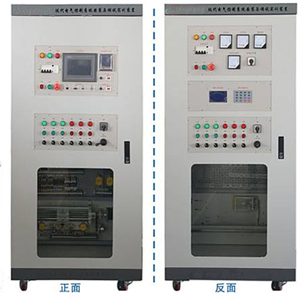
4. Product structure and composition
The equipment consists of tr*ning cabinets, door panels, electrical control components (components), instruments, tr*ning and assessment unit hanging boards, typical machine tool circuit hanging boards, motor units, motion units, temperature control components, mesh hanging boards, etc. The entire system is m*nly composed of the m*n electrical and instrument unit, PLC network configuration unit, PLC control unit, relay control unit, and typical machine tool circuit intelligent assessment unit.
1. Tr*ning cabinet: It adopts steel structure and has self-locking casters. It serves as the installation carrier for the mechanical and electrical equipment of the electrical control system. The equipment can be arranged and installed freely and flexibly.
2. M*n electrical and instrument unit: The m*n components of this unit include incoming power control and protection, m*n electrical control components, indicator lights, touch screens, display instruments, emergency stop buttons and other devices. This unit is the control signal and display (instruction) unit in the equipment. In the entire electrical control system, it plays the role of providing control signals to other units in the system.
3. PLC network configuration unit: The m*n components of this unit include Mitsubishi Q-type PLC, Mitsubishi FX3U-type PLC, analog modules, expansion modules, 0~20mA standard constant current source, 0~10V standard constant voltage source, digital Display instruments, servo drives, stepper drives, etc. The PLC network configuration unit is the m*n (host computer) control unit for electrical system program control. In the entire system, it plays an important role in input signal processing and electrical control signal output.
4. PLC control unit: The m*n components of this unit include Mitsubishi FX3U PLC, analog modules, expansion modules, 0~20mA standard constant current source, 0~10V standard constant voltage source, digital display instruments, frequency converters, etc. This unit is the auxiliary control unit for the electrical system program control (lower computer) in the equipment. It processes the input signals and outputs electrical control signals.
5. Relay control unit: The m*n components of this unit include circuit breakers, fuses, contactors, intermediate relays, thermal protection relays, travel switches, time relays, etc. At the same time, a trolley motion device driven by servo and stepper motors (which can be converted into each other) and equipped with sensors, micro switches, ball screws, and incremental encoders is also installed. This unit can realize basic motor drag control. In the entire electrical automatic control system, it plays a role in amplifying and executing PLC control signals. It can also realize independent relay drag functions.
6. Typical machine tool circuit intelligent assessment unit: The m*n components of this unit include X62W milling machine circuit, T68 boring machine circuit, computer intelligent assessment and PLC transformation module, etc. This unit completes fault inspection and elimination of machine tool circuits by analyzing and judging typical machine tool circuit fault phenomena, measuring and checking fault points, and using computer intelligent assessment software to eliminate faults.
5. Basic configuration
|
serial number |
name |
Specifications and models |
quantity |
Remark |
|
1 |
Tr*ning cabinet |
Power supply: three-phase five-wire ~ 380V±10% 50Hz Size: 850mm×800mm×1800mm Power:<1kVA |
1 set |
Steel structure, with self-locking casters, serves as the installation carrier for the mechanical and electrical equipment of the electrical control system. The equipment can be arranged and installed freely and flexibly. |
|
2 |
M*n electrical and instrumentation unit |
EA-01, EA-02 |
1 set each |
Including incoming power supply control and protection, m*n electrical control components, indicator lights, touch screens, display instruments, emergency stop buttons and other devices. Each door has a set with different configurations. |
|
3 |
PLC network configuration unit hanging board |
EA-03-01A |
1 set |
Including Mitsubishi Q type PLC, Mitsubishi FX3U type PLC, expansion modules, 0~20mA standard constant current source, 0~10V standard constant voltage source, digital display instrument, etc. |
|
4 |
PLC control unit hanging board |
EA-03A |
1 set |
Including Mitsubishi FX3U PLC, analog modules, expansion modules, 0~20mA standard constant current source, 0~10V standard constant voltage source, digital display instruments, frequency converters, Mitsubishi servo drives, Leis* stepper drives, etc. |
|
5 |
Relay control unit hanging board |
EA-04 |
1 set |
Including circuit breakers, fuses, contactors, intermediate relays, thermal protection relays, travel switches, time relays, etc. At the same time, a trolley motion device composed of servo, stepper motor drives (interconvertible), sensors, micro switches, ball screws, and incremental encoders is also installed. |
|
6 |
Typical machine tool circuit intelligent assessment unit hanging board |
EA-06, EA-07 |
1 set each |
Including X62W milling machine circuit and T68 boring machine circuit. |
|
7 |
Programmable Controllers |
Mitsubishi |
1 set |
See table 1 |
|
8 |
Frequency converter |
Mitsubishi |
1 set |
See table 1 |
|
9 |
touchscreen |
1 |
Kunlun Tongt* touch screen |
|
|
10 |
M*ntenance of electricians , electronic motors and vocational qualification tr*ning assessment simulation software |
Provide copyright certificate and on-site demonstration when bidding |
1 set |
This software is in apk format and can be used on PC or mobile. This software can set faults manually or automatically. This software can manually set fault points through the green box in the circuit diagram (you can set up to 39 fault points), you can also automatically set one random fault point, two random fault points, three random fault points, four random fault points, and five random fault points through the system. It has functions such as toolbox, component library, magnifying glass, circuit diagram, etc. You can choose a multimeter for testing through the toolbox, select appropriate components through the component library, and clearly understand each component and circuit through the magnifying glass. This software allows students to understand the working principle and circuit structure of the motor star-delta start control circuit through the setting of faults in the motor star-delta start control circuit and various investigations. |
|
11 |
Intelligent electrical control tr*ning and assessment system |
1 set |
The intelligent human-computer dialogue platform (clicker) consists of a Chinese LCD screen, a microcomputer, and a touch keyboard. Operating unit: Operating unit circuit board (integrated with display screen), keyboard. The operating unit adopts a multiple protection design; dual power supply DC 12V input; 128X64LCD display; 8 switching alarm inputs, up to 48 relay control; the operating unit can be offline for assessment without being connected to the Internet; it can automatically score; and the display prompts when there is an alarm. It m*nly has the following operating functions: (1) Student Portal: Used by students when troubleshooting to check the rem*ning assessment time. (2) Teacher entrance: set faults, resolve all faults, set assessment time, modify login password, and set device number. The teacher entrance requires a login password. (3) Score query: Query the current score of students. (4) Student ID query: Query the student ID set by the teacher through the computer. (5) Device number query: Query the local device address. Each operating unit has a unique device address. (6) Assessment time starts: After the teacher sets the assessment time, the assessment starts counting down. |
|
|
12 |
Electricity safety and electric shock first *d virtual simulation system |
Provide copyright certificate and on-site demonstration when bidding |
1 set |
The software uses a combination of two-dimensional and three-dimensional virtual images to teach students the safety and first *d methods of using electricity. The software includes single-phase electric shock, two-phase electric shock, step electric shock, low-voltage electric shock first *d, high-voltage electric shock first *d, artificial respiration first *d, Principles of hand-holding breathing rescue method, chest cardiac compression and other protective methods are expl*ned and taught. Principles of single-phase electric shock are divided into rep*ring live disconnection, rep*ring socket electric shock, and outdoor electric shock. The teaching of low-voltage electric shock and high-voltage electric shock m*nly expl*ns and demonstrates to students how to rescue people who are suffering from low-voltage electric shock or high-voltage electric shock. Artificial respiration rescue method, hand-holding breathing rescue method, and chest cardiac compression rescue method are demonstrated using 3D virtual simulation technology. After rendering and Polish it to make the model look like the real part and look realistic. Through practical tr*ning, students can be educated on the safe use of electricity in the tr*ning room, improve students' safety awareness, and enable students to learn some self-rescue methods, so that students can take cert*n safety measures to protect themselves when encountering danger, and become familiar with various Causes of electrical accidents and practical measures to deal with them to reduce the occurrence of electrical accidents. |
|
13 |
Virtual spectrum analyzer, logic analyzer, oscilloscope, three-meter simulation software |
Provide copyright certificate and on-site demonstration when bidding |
1 set |
This software is in apk format and can be used on PC or mobile terminals. The functions of this software are: resistance measurement, AC voltage measurement (measuring transformer, if the multimeter burns out when measuring the transformer, black smoke will emit prompts and can reset the multimeter), determine the polarity of the transistor, measure the DC voltage (the light turns on when the ammeter is turned on), measure the DC current, and determine the quality of the capacitor. This software can drag the red and black pen tips at will. When the two pen tips are dragged and positioned on the measured object, a red circle will be displayed. If the positioning is not accurate, no red circle will be displayed, and when incorrect operations are performed (such as the wrong range selected, If the measured data is wrong, etc.), the meter pointer will not respond, prompting errors and re-measurement, etc. This multimeter can select AC voltage range, DC voltage range, resistance range, current range, resistance adjustment to 0, and can enlarge the display data. Clearly view the measured data size. Students can learn the correct use of multimeters through this software. |
|
14 |
Microcontroller , PLC programmable design and control virtual simulation software |
Provide copyright certificate and on-site demonstration when bidding |
1 set |
This software is developed based on unity3d and has built-in experimental steps, experimental instructions, circuit diagrams, component lists, connection lines, power on, circuit diagrams, scene reset, return and other buttons. After the connections and codes are correct, you can start/stop, The forward movement and reverse movement buttons operate the 3D machine tool model to move. In the connected line state, the 3D machine tool model can be enlarged/reduced and translated. 1. Relay control: Read the experiment instructions and enter the experiment. By reading the circuit diagram, select the relays, thermal relays, switches and other components in the component list and drag and drop them into the electrical cabinet. The limiters are placed in the three-dimensional On the machine tool model, you can choose to cover it, and some component names can be renamed. Then click the Connect Line button to connect terminals to terminals. After successfully connecting the machine tool circuit, choose to turn on the power and proceed. If the component or line An error box will pop up if there is a connection error, and the scene can be reset at any time. 2. PLC control: The experiment is the same as relay control, with the addition of PLC control function. After the connection is completed, enter the program writing interface through the PLC coding button, and write two programs, forward and reverse, with a total of 12 ladder diagram symbols. The writing is completed. Finally, select Submit for program verification. After the verification is successful, turn on the power for operation. Error boxes will pop up for component, line connection, and code errors, and the scene can be reset at any time. 3. Single-chip microcomputer control: The experiment is the same as relay control, with the addition of single-chip microcomputer control function. After the connection is completed, enter the programming interface through the C coding button, enter the correct C language code, and after successful submission and verification, turn on the power for operation, components, lines If there are connection or code errors, an error box will pop up, and the scene can be reset at any time. |
|
15 |
tool |
Wire strippers, diagonal pliers, slotted screwdriver, Phillips screwdriver, Allen wrench, small adjustable wrench, etc. |
1 set |
|
|
16 |
Computer Desk |
1 set |
Table 1: PLC and inverter configuration
|
serial number |
name |
Model/specification/number |
unit |
quantity |
|
1 |
Mitsubishi module |
Q00UCPU |
piece |
1 |
|
2 |
Mitsubishi power supply unit base plate |
Q35B |
strip |
1 |
|
3 |
Mitsubishi module |
Q61P |
piece |
1 |
|
4 |
Mitsubishi module |
QX40 |
piece |
1 |
|
5 |
Mitsubishi output module |
QY10 |
piece |
1 |
|
6 |
Mitsubishi cclink communication module |
QJ61BT11N |
piece |
1 |
|
7 |
Mitsubishi communication line |
QC30R2 |
strip |
1 |
|
8 |
Mitsubishi programmable controller |
FX3U-32MR/ES-A |
indivual |
1 |
|
9 |
Mitsubishi programmer |
FX3U-32MT/ES-A |
indivual |
1 |
|
10 |
Mitsubishi module |
FX3U-3A-ADP |
indivual |
1 |
|
11 |
Mitsubishi cclink communication module |
FX2N-32CCL |
indivual |
2 |
|
12 |
FX series download line |
RS-232 |
strip |
1 |
|
13 |
485 communication module |
FX3U-485-BD |
indivual |
2 |
|
14 |
Mitsubishi inverter |
FR-E740-0.75K-CH |
tower |
1 |
6. Practical tr*ning projects
1. Connect the transfer switch to the voltmeter to measure the three-phase voltage.
2. Measurement of three-phase current
3. Use of comprehensive power meters
4. Control of direct starting and stopping of three-phase asynchronous motors
5. Contactor interlocking three-phase AC asynchronous motor forward and reverse control circuit
6. Button interlocking three-phase AC asynchronous motor forward and reverse control circuit
7. Three-phase AC asynchronous motor forward and reverse control circuit with button and contactor interlocking
8. Three-phase AC asynchronous motor Y-△ (manual switching) starting control circuit
9. Three-phase AC asynchronous motor Y-△ (time relay switching) starting control circuit
10. Stator winding series resistance starting control circuit
11. Three-phase AC asynchronous motor energy consumption braking control circuit
12. Three-phase AC asynchronous motor reduced voltage starting and reverse braking control circuit
13. Sequential control circuit of two motors
14. Motor round trip control circuit
15. Ordinary lathe control circuit
16. Electric hoist control circuit
17. Three-phase AC asynchronous motor control circuit for inching and continuous rotation
18. Two-place control circuit
19. Contactor controlled two-speed motor speed control circuit
20. Two-speed motor speed control circuit with time relay switching
21. Reverse braking control with centrifugal switch
22. Inverter panel function parameter setting and operation
23.External terminal jog control
24. Motor multi-stage speed control
25. Power frequency and variable frequency switching control
26. Frequency conversion open-loop speed control based on PLC analog method
27. Motor open-loop speed regulation based on panel operation
28. Open-loop speed regulation of frequency converter based on PLC communication
29. PLC controls the sequential starting of motors
30. Parameter setting and programming of touch screen
31. Touch screen configuration controls three-phase asynchronous motor jogging and self-locking
32. Touch screen configuration controls forward and reverse rotation of three-phase asynchronous motor
33. Touch screen configuration controls three-phase asynchronous motor star-delta starting
34. Touch screen configuration controls inverter analog speed regulation
35. Parameter setting of stepper driver
36. Stepper motor control
37. PLC open-loop control of stepper motor
38.Use of encoder
39. Encoder-based stepper motor closed-loop control
40. Parameter settings of AC servo drive
41. Closed-loop control of AC servo motor
42. Debugging of temperature controller and use of thermal resistors
43. PLC temperature control based on thermal resistance
44. Use of sensors
45. Sensor-based PLC position control
46. Communication between multiple PLC master and slave stations
47. Practical tr*ning on inspection and troubleshooting of common faults in the electrical control circuit unit of X62W milling machine
48.T68 boring machine electrical control circuit unit common fault inspection and elimination
Hot-selling product: Electrician tr*ning bench
 Wechat scan code follow us

24-hour hotline+86 18916464525

Phone18916464525
ADD:Factory 414, District A, No. 6, Chongnan Road, Songjiang Science and Technology Park, Shanghai ICP: Sitemap