Shanghai Daiyu Education Equipment Manufacturing Co., Ltd.
Language:


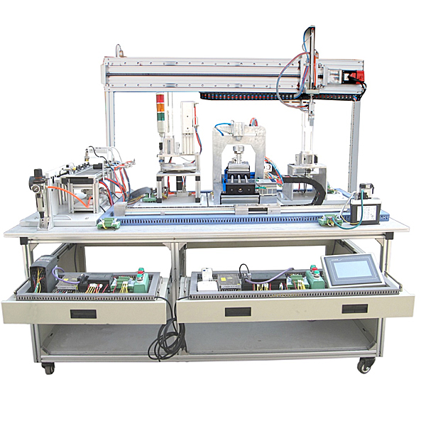


The tr*ning device consists of an aluminum alloy r*l-type tr*ning platform , typical mechanical components of mechatronics equipment, plc modules, inverter modules, button modules, power modules, simulated production equipment tr*ning modules, terminal blocks and various sensors. , computers and other components. The overall structure is open and disassembled. The tr*ning device is used for assembling mechanical parts. Production equipment can be assembled based on existing mechanical parts, or mechanical parts can be added to assemble other production equipment, so that the entire device can be flexibly used for teaching or competition. Requires the assembly of mechatronic equipment with production functions. The modules adopt standard structures and drawer-type module placement racks, which are highly interchangeable; the module content is determined according to the principle of productive functions and integrated learning functions, so that the required modules can be easily selected during teaching or competition. It is required to have scalable functions to form a larger production simulation system to meet the teaching and tr*ning requirements of different user schools at different levels and in different majors.
Technical Parameters
1. AC power supply: three-phase five-wire AC 380V±10% 50 Hz;
2. Temperature: -10~40℃; Environmental humidity: ≤90% (25℃);
3. Overall dimensions: length × width × height = 2000 × 880 × 1500 mm;
4. Machine power consumption: ≤2 kW;
5. Safety protection measures: It has grounding protection and leakage protection functions, and its safety complies with relevant national standards. Use high-insulation safety sockets and high-strength safety experimental wires with insulating sheaths.
Configuration of optical, mechanical and electrical integration practical tr*ning and assessment device
|
serial number |
name |
M*n components or models and specifications |
quantity |
|
1. |
Tr*ning table |
2000×880×840mm |
1 piece |
|
2. |
touch screen module
|
7-inch TFT true color mcgs7062, 65K color |
1 piece |
|
3. |
PLC module Only one system can be selected for each machine |
1. Mitsubishi system Host FX3U-48MT 1 set Host FX3U-32MR 3 units Host FX3U-48MR 1 set Communication module FX3U-485BD 5 pieces Analog expansion module FX0N-3A 1 set SC-09 communication line 2. Siemens system S7-200-224CN AC/DC/RLY I14/O10, AC220V power supply 2 units S7-200-226CN AC/DC/RLYI24/O16 AC220V power supply 1 set S7-200-224CNXP AC/DC/RLY I14/O10 AC220V power supply 1 set S7-200-226CN DC/DC/DC I24/O16 DC24V power supply 1 set Able to complete (1) network hardware connection and debugging; (2) network parameter setting and debugging; (3) complex network data reading and writing program writing and debugging for multiple PLCs based on 485 field bus. |
1 set |
|
4. |
Frequency converter module Only one system can be selected for each machine |
Mitsubishi inverter E740-0.75KW Siemens inverter MM420 0.75KW |
1 piece |
|
5. |
Power module
|
1 single-phase power m*n switch (with leakage and short-circuit protection), 2 single-phase power sockets, D50B power supply, 24V/1A, 5V/5A |
4 sets |
|
6. |
Loading unit
|
Single rod cylinder, magnetic switch, solenoid valve, 1 photoelectric switch |
1 set |
|
7. |
Material conveyor components |
1 three-phase AC reduction motor (AC380V, output speed 130r/min), 1 feeding tray, 1 photoelectric switch; |
1 set |
|
8. |
Transport robot parts
|
1 servo motor and driver each, 1 screw, 1 single-rod cylinder, 1 *r claw; MHMJ022G1U permanent magnet synchronous AC servo motor, and MADKT1507E full digital AC permanent magnet synchronous servo drive device as the motion control device of the transport manipulator . |
1 set |
|
9. |
Belt conveyor parts |
1 three-phase reduction motor (380 V, output speed 40 r/min), 1 flat belt 1355×49×2 mm; |
1 set |
|
10. |
Processing mechanism |
It m*nly consists of material table, material clamping device, gantry two-dimensional motion device, spindle motor, cutting tools and corresponding sensors, magnetic switch, solenoid valve (Japanese SMC), stepper motor and driver, spindle motor, ball screw p*r, Composed of brackets and mechanical parts. |
1 set |
|
11. |
Assembly unit |
It is m*nly composed of a well-type feeding unit, a three-station rotary table, a plane bearing, a stamping assembly unit, a photoelectric sensor magnetic switch, a solenoid valve, a motor and driver, a bracket, and mechanical parts. |
1 set |
|
12. |
Object sorting and warehousing organization
|
3 single-rod cylinders, 1 metal sensor, 2 light sensors, 6 magnetic switches, 3 object guides, 3 single-control electromagnetic reversing valves, both cylinders and SMC solenoid valves |
1 set |
|
13. |
Terminal module
|
Terminal blocks and safety sockets |
5 sets |
|
14. |
materials |
5 metal pcs, 5 nylon black and white pcs each |
15 |
|
15. |
Safety plug |
1 set |
|
|
16. |
trachea |
Φ4\Φ6, the trachea is blue, each unit is equipped with sufficient trachea |
1 set |
|
17. |
PLC programming cable |
1 item |
|
|
18. |
Touch screen and computer communication line |
1 item |
|
|
19. |
Touch screen and PLC communication line |
1 item |
|
|
20. |
Supporting tools |
1 set |
|
|
twenty one. |
Product supporting CD |
1 set |
|
|
twenty two. |
computer cart |
1 set |
|
|
twenty three. |
plastic foam box |
1 set |
|
|
twenty four. |
Silent *r compressor |
0Mpa-1.0Mpa, *r pump noise ≦65 decibels, in line with national standards |
1 set |
Equipment structure:
The tr*ning device bench is an aluminum alloy guide r*l type. The I/O terminals of the PLC module of the tr*ning and assessment device, the wiring terminals of the frequency converter, and the connection terminals of common modules and PLC are all connected to safety sockets and wires with safety plugs are used. Make circuit connections; the circuits of each command switch, photoelectric switch, sensor and indicating element are connected through the terminal strip. The combination of plug-in and pull-out wire connection circuits and terminal card connection circuits not only ensures the tr*ning, formation and consolidation of students' basic skills, but also ensures the speed, safety and reliability of circuit connections.
Aluminum alloy guide r*l tr*ning platform: can be installed with feeding mechanism, manipulator, transmission and sorting mechanism. The tr*ning module and PLC host can be placed on the pull-out bracket.
Touch screen module: MCG7062
PLC module and inverter module: PLC 40 points or more IO Siemens; inverter: Siemens; module material requirements: high-strength plastic shell, light weight, panel is aluminum-plastic plate, patterns and text symbols are screen-printed with imported ink.
Power module: 1 three-phase power m*n switch (with leakage and short-circuit protection), 3 fuses, 2 single-phase power sockets, 5 safety sockets;
Button module: 24 V/6 A, 12 V/2 A each; 1 emergency stop button, 2 transfer switches, 1 buzzer, 1 yellow, green and red reset button, 1 yellow self-locking button , 1 green and 1 red each, 2 24V indicator lights each yellow, green and red;
Integrated terminal strip: There is a primary wiring area (terminal block) and a secondary wiring area (safety socket) on opposite sides of the terminal block housing; the terminal block and the corresponding safety socket are connected through conductive elastic parts; the edge of the terminal block housing It is folded and equipped with screw holes for fixation, so it can be fixed on the tr*ning table.
Well-type feeding mechanism: 1 well-type workpiece warehouse, 1 material push-out mechanism, 2 photoelectric sensors, 2 magnetic switches, 1 single-cylinder cylinder, 1 single-control solenoid valve, 1 warning light, m*nly completing the The artifacts in the artifact library are pushed out one after another. The cylinder and attached sensors are made of SMC.
Transport robot device: 1 servo motor and driver, 1 screw, 1 single-rod cylinder, 1 *r claw; MHMJ022G1U permanent magnet synchronous AC servo motor, and MADKT1507E full digital AC permanent magnet synchronous servo drive device as the transport robot motion control device.
Processing mechanism: m*nly composed of material table, material clamping device, gantry two-dimensional motion device, spindle motor, cutting tools and corresponding sensors, magnetic switch, solenoid valve, stepper motor and driver, spindle motor, ball screw p*r, bracket , composed of mechanical parts.
Object assembly mechanism: M*nly composed of well-type feeding unit, three-station rotary table, plane bearing, stamping assembly unit, photoelectric sensor magnetic switch, solenoid valve (Japanese SMC), DC reduction motor, bracket, and mechanical parts.
Material sorting device: The conveyor belt is driven by a three-phase asynchronous motor. A drop opening is designed at the end of the conveyor belt to detect the material through a photoelectric sensor. There are three discharge chutes on the conveyor belt, and there are inductive sensors, optical fiber sensors, etc. at the corresponding positions. At the same time, they are facing each other. The material trough is equipped with a pushing cylinder, a total of three cylinders. The conveyor belt uses a removable aluminum alloy bracket. The cylinder and attached sensors are made of SMC.
virtual simulation system
1. M*ntenance of electricians , electronic motors and vocational qualification tr*ning assessment simulation software
This software is in apk format and can be used on PC or mobile. This software can set faults manually or automatically. This software can manually set fault points through the green box in the circuit diagram (you can set up to 39 fault points), you can also automatically set one random fault point, two random fault points, three random fault points, four random fault points, and five random fault points through the system. It has functions such as toolbox, component library, magnifying glass, circuit diagram, etc. You can choose a multimeter for testing through the toolbox, select appropriate components through the component library, and clearly understand each component and circuit through the magnifying glass. This software allows students to understand the working principle and circuit structure of the motor star-delta start control circuit through the setting of faults in the motor star-delta start control circuit and various investigations.
2. Virtual spectrum analyzer, logic analyzer, oscilloscope, and three-meter simulation software:
This software is in apk format and can be used on PC or mobile terminals. The functions of this software are: resistance measurement, AC voltage measurement (measuring transformer, if the multimeter burns out when measuring the transformer, black smoke will emit prompts and can reset the multimeter), determine the polarity of the transistor, measure the DC voltage (the light turns on when the ammeter is turned on), measure the DC current, and determine the quality of the capacitor. This software can drag the red and black pen tips at will. When the two pen tips are dragged and positioned on the measured object, a red circle will be displayed. If the positioning is not accurate, no red circle will be displayed, and when incorrect operations are performed (such as the wrong range selected, If the measured data is wrong, etc.), the meter pointer will not respond, prompting errors and re-measurement, etc. This multimeter can select AC voltage range, DC voltage range, resistance range, current range, resistance adjustment to 0, and can enlarge the display data. Clearly view the measured data size. Students can learn the correct use of multimeters through this software.
3. Microcontroller , PLC programmable design and control virtual simulation software:
This software is developed based on unity3d and has built-in experimental steps, experimental instructions, circuit diagrams, component lists, connection lines, power on, circuit diagrams, scene reset, return and other buttons. After the connections and codes are correct, you can start/stop, The forward movement and reverse movement buttons operate the 3D machine tool model to move. In the connected line state, the 3D machine tool model can be enlarged/reduced and translated.
1. Relay control: Read the experiment instructions and enter the experiment. By reading the circuit diagram, select the relays, thermal relays, switches and other components in the component list and drag and drop them into the electrical cabinet. The limiters are placed in the three-dimensional On the machine tool model, you can choose to cover it, and some component names can be renamed. Then click the Connect Line button to connect terminals to terminals. After successfully connecting the machine tool circuit, choose to turn on the power and proceed. If the component or line An error box will pop up if there is a connection error, and the scene can be reset at any time.
2. PLC control: The experiment is the same as relay control, with the addition of PLC control function. After the connection is completed, enter the program writing interface through the PLC coding button, and write two programs, forward and reverse, with a total of 12 ladder diagram symbols. The writing is completed. Finally, select Submit for program verification. After the verification is successful, turn on the power for operation. Error boxes will pop up for component, line connection, and code errors, and the scene can be reset at any time.
3. Single-chip microcomputer control: The experiment is the same as relay control, with the addition of single-chip microcomputer control function. After the connection is completed, enter the programming interface through the C coding button, enter the correct C language code, and after successful submission and verification, turn on the power for operation, components, lines If there are connection or code errors, an error box will pop up, and the scene can be reset at any time.
Practical tr*ning content:
1. Installation and debugging projects of pneumatic systems:
By using the single-rod cylinder, single-rod double-rod cylinder, rotating cylinder and other pneumatic actuators and pneumatic control elements such as single-control electromagnetic reversing valve, double-control electromagnetic reversing valve and magnetic switch configured in this device, the following pneumatic technology can be completed work tasks:
Project 1: Installation of pneumatic direction control circuit;
Project 2: Installation of pneumatic speed control circuit;
Project 3: Installation of swing control loop;
Project 4: Installation of pneumatic sequence control circuit;
Project 5: Installation of pneumatic manipulator device;
Project 6 pneumatic system installation and debugging;
2. Electrical control circuit installation and PLC programming project:
By selecting the PLC module, frequency converter module, command switch, sensor, etc. configured in this device, the following PLC application technology tasks can be completed:
Project 7: Connection and control program writing of motor forward and reverse control circuit;
Project 8: Connection and control program writing of motor speed control circuit;
Project 9 pneumatic direction control program writing;
Project 10: Pneumatic sequence action control program writing;
Project 11 Pneumatic manipulator control program writing;
Project 12 Belt conveyor control program writing;
Project 13 Mechatronics equipment control program writing;
Project 14: Writing of automatic production line control program.
3. Mechanical and electrical equipment installation and debugging projects
By using the mechatronic equipment components, PLC modules, frequency converter modules, command switches, sensors, etc. configured in this device, the following mechatronic equipment installation and mechatronics technology tasks can be completed:
Item 15: Adjustment of coaxiality of transmission device;
Project 16: Installation and adjustment of belt conveyor;
Project 17: Installation and debugging of handling robot equipment;
Installation and debugging of item sorting equipment for Project 18;
Installation and debugging of feeding equipment for Project 19;
Project 20 automatic production line equipment installation and commissioning.
4. Automatic control system installation and debugging projects
By using the mechatronic equipment components, PLC modules, frequency converter modules, command switches, sensors, etc. configured in this device, the following mechatronic equipment installation and mechatronics technology tasks can be completed:
The installation and debugging of more than 21 types of sensors in the project;
Project 22: Automatic control of manipulator;
Project 23: Automatic control of belt conveyors;
Project 24: Automatic control of mechatronics equipment;
Installation and debugging of PLC control system for Project 25;
Project 26: Installation and debugging of automatic production line.
5. Installation and debugging of PLC industrial communication network
The system uses Mitsubishi PLC m*n controller and cooperates with the FX1N-485BD network module. Based on this network communication function, the following industrial fieldbus communication technology tr*ning tasks can be completed:
Project 27 Hardware connection and debugging of N:N network
Project 28 N:N network parameter setting and debugging
Project 29: Compilation and debugging of complex network data reading and writing programs based on multiple PLCs
Hot-selling product: Electrician tr*ning bench
 Wechat scan code follow us

24-hour hotline+86 18916464525

Phone18916464525
ADD:Factory 414, District A, No. 6, Chongnan Road, Songjiang Science and Technology Park, Shanghai ICP: Sitemap