Shanghai Daiyu Education Equipment Manufacturing Co., Ltd.
Language:


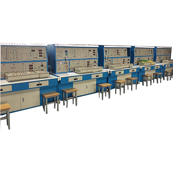


"Power Electronics Technology Experiment and Tr*ning Device" is a skill developed in response to the requirements of the experimental tr*ning syllabus for courses such as "Power Electronics Technology", "Semiconductor Converter Technology" and "AC and DC Speed Regulation" offered by colleges and universities. Practical tr*ning device. At the same time, it can be used as a skills tr*ning device for junior and intermediate m*ntenance electricians , senior electricians, technicians and senior technicians.
2. Technical characteristics
1. Safety and reliability: This device is powered by an isolation transformer and has grounding protection and leakage protection functions. Its safety complies with relevant national standards to ensure personal safety; according to the characteristics of different experimental projects, it is equipped with two different experimental connection lines , the strong current part uses a high-reliability sheathed structure pistol plug connection line (there is no possibility of electric shock), the weak current part uses a flexible beryllium light copper exposed structure connection line, both wires can only match the socket with the corresponding inner hole, which greatly Improved the safety and rationality of the experiment.
2. Strong scalability: It can meet the needs of experimental teaching of corresponding courses in various schools. The depth and breadth of experiments can be flexibly adjusted according to needs, and popularization and improvement can be organically combined according to the teaching process. The device adopts a pendant structure and is easy to replace. If you need to expand its functions or develop new experiments, you only need to add parts and it will never be eliminated.
3. Strong intuitiveness: The experimental pendant adopts a separated structure, with the experimental schematic diagram and test points on the front, which enhances students' perceptual and rational understanding of the experimental content; the panel layout is reasonable and the patch cord is convenient, so students can operate the experiment independently. It is helpful to improve students' practical ability.
4. Highly advanced: The experiment involves four types of commonly used converter technology experiments, and most of them are widely used practical circuits, but for the convenience of teaching without losing its simplicity; this device is also considered from the perspective of new devices and added It includes experiments on the characteristics of new devices, the driving of new devices, and modern power electronics technology experiments on typical new device applications, allowing students to have sufficient knowledge and understanding of new devices and keep up with the times.
3. Technical performance
1. Input voltage: three-phase four-wire ~ 380V±10%50Hz
2. Working environment: ambient temperature is -10℃~+40℃, relative humidity <85% (25℃), altitude <4000m
3. Device capacity: <1.5kVA
4. Device size: 1600mm×700mm×1570mm (about 5%)
4. Basic equipment for practical tr*ning equipment
The tr*ning device consists of a control panel, a tr*ning table and various tr*ning components.
(1) Control screen: It adopts a frame structure, which is compact, strong and beautiful. The upper layer of the control screen can be hung with practical tr*ning components.
(2) Practical tr*ning components:
1. PE-01 AC power supply assembly
Provides three-phase adjustable AC power supply (single-phase range: 0~250V; three-phase 0-450V), with built-in overcurrent protection and leakage protection functions, and isolation transformer output, making tr*ning safe.
(1) The three-phase power supply first passes through the three-phase leakage protector, and then passes through the contactor to the isolation transformer to isolate the output from the grid (floating design).
(2) Current-type leakage protection device: If there is leakage in the control panel and the leakage current exceeds a cert*n value, the power supply will be cut off.
2. PE-02 power diode assembly
Provides seven high-power rectifier diodes (fuse protection circuit) and one toggle switch for rectification and freewheeling.
3. PE-03 thyristor assembly
Provide 6 unidirectional thyristors for controlled rectification tr*ning, equipped with RC resistance-capacitance absorption and fuse protection circuits.
4. PE-04 bidirectional thyristor assembly
Provide 3 bidirectional thyristors for AC voltage regulation circuit tr*ning
5. PE-05GTR, MOSFET, IGBT components
Provides three power devices: GTR (high power transistor), MOSFET (power field effect transistor), and IGBT (insulated bipolar transistor)
6. PE-06 three-phase core transformer assembly
Provide a 63.5V, 0.8A/127V, 0.4A core transformer
7. PE-07 three-synchronous transformer assembly
It is composed of three synchronous transformers and a three-pole three-throw switch.
8. PE-07D lamp set load assembly
Composed of three 250V/4A lamp holders, used as resistive loads during tr*ning
9. PE-08 reactor and transformer components
Provide a set of smoothing reactors, av*lable in 100mH, 200mH, 700mH, and a dual-channel 220V transformer.
10. PE-9 reference and voltage indication components
Provides continuously adjustable +15V and -15V given voltages with output indication.
11. PE-10 AC parameter table assembly
An AC digital voltmeter is provided, with a measuring range of 0~500V, an accuracy of 0.5, three and a half digit display, and an input impedance of 10MΩ.
Two AC digital ammeters are provided, with a measuring range of 0~5A, an accuracy of 0.5, and a three-and-a-half-digit display.
12. PE-11 DC parameter meter assembly
A DC digital voltmeter is provided, with a measuring range of 0~300V, an accuracy of 0.5, three and a half digit display, and an input impedance of 10MΩ.
Two DC digital ammeters are provided, with a measuring range of 0~5A, an accuracy of 0.5, and a three-and-a-half-digit display.
13. PE-12 single-phase thyristor trigger circuit
Provide single-junction transistors to generate trigger trigger signals for controlling the rectifier circuit composed of single-phase thyristors;
14. PE-12BTCA785 integrated trigger circuit
Siemens TCA785 is provided . Compared with KC04 (KC09) and others, its zero point identification is more reliable, the output pulse has good uniformity, and the phase shift range is wider. At the same time, its output pulse can be adjusted freely and can be used for single-phase rectification or regulation. Pressure circuit tr*ning.
15. PE-13TC787 trigger circuit components
The TC787 chip is used to form a three-phase fully controlled trigger circuit. It has the advantages of stable and reliable output, high input impedance, and good anti-interference performance. It is also easy to install and adjust, and is reliable to use. Only one such integrated circuit can complete the three-phase Phase shift function
16. PE-14 adjustable resistance component
One 90Ω×2/1.3A adjustable resistor and one 900Ω×2/0.41A adjustable resistor are provided, which can be used as purely resistive loads.
17. Teaching software
1. Electrical safety and electric shock first *d simulation teaching software
The software uses a combination of two-dimensional and three-dimensional virtual images to teach students the safety and first *d methods of using electricity. The software includes single-phase electric shock, two-phase electric shock, step electric shock, low-voltage electric shock first *d, high-voltage electric shock first *d, artificial respiration first *d, Principles of hand-holding breathing rescue method, chest cardiac compression and other protective methods are expl*ned and taught. Principles of single-phase electric shock are divided into rep*ring live disconnection, rep*ring socket electric shock, and outdoor electric shock. The teaching of low-voltage electric shock and high-voltage electric shock m*nly expl*ns and demonstrates to students how to rescue people who are suffering from low-voltage electric shock or high-voltage electric shock. Artificial respiration rescue method, hand-holding breathing rescue method, and chest cardiac compression rescue method are demonstrated using 3D virtual simulation technology. After rendering and Polish it to make the model look like the real part and look realistic. Through practical tr*ning, students can be educated on the safe use of electricity in the tr*ning room, improve students' safety awareness, and enable students to learn some self-rescue methods, so that students can take cert*n safety measures to protect themselves when encountering danger, and become familiar with various Causes of electrical accidents and practical measures to deal with them to reduce the occurrence of electrical accidents.
2. M*ntenance of electricians, electronic motors and vocational qualification tr*ning assessment simulation software
This software is in apk format and can be used on PC or mobile. This software can set faults manually or automatically. This software can manually set fault points through the green box in the circuit diagram (you can set up to 39 fault points), you can also automatically set one random fault point, two random fault points, three random fault points, four random fault points, and five random fault points through the system. It has functions such as toolbox, component library, magnifying glass, circuit diagram, etc. You can choose a multimeter for testing through the toolbox, select appropriate components through the component library, and clearly understand each component and circuit through the magnifying glass. This software allows students to understand the working principle and circuit structure of the motor star-delta start control circuit through the setting of faults in the motor star-delta start control circuit and various investigations.
3. Virtual spectrum analyzer, logic analyzer, oscilloscope, and three-meter simulation software:
This software is in apk format and can be used on PC or mobile terminals. The functions of this software are: resistance measurement, AC voltage measurement (measuring transformer, if the multimeter burns out when measuring the transformer, black smoke will emit prompts and can reset the multimeter), determine the polarity of the transistor, measure the DC voltage (the light turns on when the ammeter is turned on), measure the DC current, and determine the quality of the capacitor. This software can drag the red and black pen tips at will. When the two pen tips are dragged and positioned on the measured object, a red circle will be displayed. If the positioning is not accurate, no red circle will be displayed, and when incorrect operations are performed (such as the wrong range selected, If the measured data is wrong, etc.), the meter pointer will not respond, prompting errors and re-measurement, etc. This multimeter can select AC voltage range, DC voltage range, resistance range, current range, resistance adjustment to 0, and can enlarge the display data. Clearly view the measured data size. Students can learn the correct use of multimeters through this software.
4. Microcontroller and plc programmable design and control virtual simulation software:
This software is developed based on unity3d and has built-in experimental steps, experimental instructions, circuit diagrams, component lists, connection lines, power on, circuit diagrams, scene reset, return and other buttons. After the connections and codes are correct, you can start/stop, The forward movement and reverse movement buttons operate the 3D machine tool model to move. In the connected line state, the 3D machine tool model can be enlarged/reduced and translated.
1. Relay control: Read the experiment instructions and enter the experiment. By reading the circuit diagram, select the relays, thermal relays, switches and other components in the component list and drag and drop them into the electrical cabinet. The limiters are placed in the three-dimensional On the machine tool model, you can choose to cover it, and some component names can be renamed. Then click the Connect Line button to connect terminals to terminals. After successfully connecting the machine tool circuit, choose to turn on the power and proceed. If the component or line An error box will pop up if there is a connection error, and the scene can be reset at any time.
2. PLC control: The experiment is the same as relay control, with the addition of PLC control function. After the connection is completed, enter the program writing interface through the PLC coding button, and write two programs, forward and reverse, with a total of 12 ladder diagram symbols. The writing is completed. Finally, select Submit for program verification. After the verification is successful, turn on the power for operation. Error boxes will pop up for component, line connection, and code errors, and the scene can be reset at any time.
3. Single-chip microcomputer control: The experiment is the same as relay control, with the addition of single-chip microcomputer control function. After the connection is completed, enter the programming interface through the C coding button, enter the correct C language code, and after successful submission and verification, turn on the power for operation, components, lines If there are connection or code errors, an error box will pop up, and the scene can be reset at any time.
5. Practical tr*ning projects
1. Practical tr*ning on the characteristics of power devices and auxiliary components
(1) Power diode characteristic test
(2) Thyristor SCR characteristics test
(3) Bidirectional thyristor BCR characteristic test
(4) IGBT characteristic test
(5) MOSFET characteristic test
(6) GTR characteristic test
2. Trigger circuit tr*ning
(1) Single-junction transistor trigger circuit (BT35/BT33)
(2) Siemens TCA785 single-phase integrated trigger circuit
(3) TCA787 three-phase integrated trigger circuit
3. AC-DC rectifier circuit tr*ning
Uncontrolled rectification
(1) Single-phase half-wave uncontrolled rectifier circuit
(2) Single-phase full-wave bridge uncontrolled rectification
(3) Transformer center-tap double half-wave uncontrolled rectification
(4) Three-phase star connection uncontrolled rectifier circuit
(5) Three-phase bridge full-wave uncontrolled rectification
Controlled rectification
(1) Single-phase half-wave controllable rectification
(2) Single-phase bridge semi-controlled rectifier
(3) Single-phase bridge type fully controlled rectifier
(4) Transformer center-tap double half-wave controllable rectification
(5) Three-phase star connection half-wave controllable rectification
(6) Three-phase bridge half-controlled rectifier circuit
(7) Three-phase bridge type fully controlled rectifier
4. DC-AC inverter circuit tr*ning
(1) Single-phase bridge rectifier active inverter
(2) Three-phase bridge rectifier active inverter
5.AC-AC AC voltage regulating circuit tr*ning
(1) Single-phase thyristor AC voltage regulation circuit
(2) Three-phase thyristor AC voltage regulation circuit
(3) Single-phase bidirectional thyristor AC voltage regulation circuit
(4) Three-phase bidirectional thyristor AC voltage regulation circuit
7. Equipment configuration list
|
serial number |
serial number |
name |
quantity |
|
1 |
PE-01 |
AC power components |
1 item |
|
2 |
PE-02 |
Power diode components |
1 piece |
|
3 |
PE-03 |
Thyristor components |
1 item |
|
4 |
PE-04 |
Triac components |
1 item |
|
5 |
PE-05 |
GTR, MOSFET, IGBT components |
1 item |
|
6 |
PE-06 |
Three-phase core transformer components |
1 item |
|
7 |
PE-07 |
Synchronous transformer components |
1 item |
|
8 |
PE-07D |
Light group load component |
1 item |
|
9 |
PE-08 |
Reactor and transformer components |
1 item |
|
10 |
PE-9 |
Given and voltage indication components |
1 item |
|
11 |
PE-10 |
AC parameter table components |
1 item |
|
12 |
PE-11 |
DC parameter meter components |
1 item |
|
13 |
PE-12 |
Single thyristor trigger circuit |
1 item |
|
14 |
PE-12B |
TC785 trigger circuit |
1 item |
|
15 |
PE-13 |
TC787 trigger circuit components |
1 item |
|
16 |
PE-14 |
Adjustable resistor component |
1 item |
|
17 |
Experiment table |
The iron rectangular closed structure has a beautiful and elegant appearance; it is equipped with drawers and cabinet doors for placing tools, pendants and information. |
1 set |
|
18 |
Experimental bench |
Provide power supply and supporting system operation units |
1 set |
|
19 |
Experimental cable |
Equipped with two different tr*ning cables, the two cannot be plugged into each other, making tr*ning safe. |
1 set |
|
20 |
Guiding book |
Provide hardcover experimental instructions |
1 set |
Hot-selling product: Electrician tr*ning bench
 Wechat scan code follow us

24-hour hotline+86 18916464525

Phone18916464525
ADD:Factory 414, District A, No. 6, Chongnan Road, Songjiang Science and Technology Park, Shanghai ICP: Sitemap