Shanghai Daiyu Education Equipment Manufacturing Co., Ltd.
Language:


"ZRBP-03C type AC and DC speed regulation tr*ning and assessment device" is developed for the skill tr*ning and assessment of senior m*ntenance electricians and technicians. It can also be used as a "power electronics technology" and "electric drag automatic control system" in various vocational colleges. , "AC/DC Speed Regulation" and other courses' practical tr*ning equipment, with fault setting and troubleshooting functions.
2. Technical performance
1. Input power: three-phase four-wire (or three-phase five-wire) ~ 380V ±10% 50Hz
2. Working environment: temperature -10℃~+40℃, relative humidity <85% (25℃), altitude <4000m
3. Device capacity: ≤1.5kVA
4. Safety protection measures: It has functions such as leakage protection and overcurrent protection, and its safety complies with relevant national standards.
3. Equipment and equipment
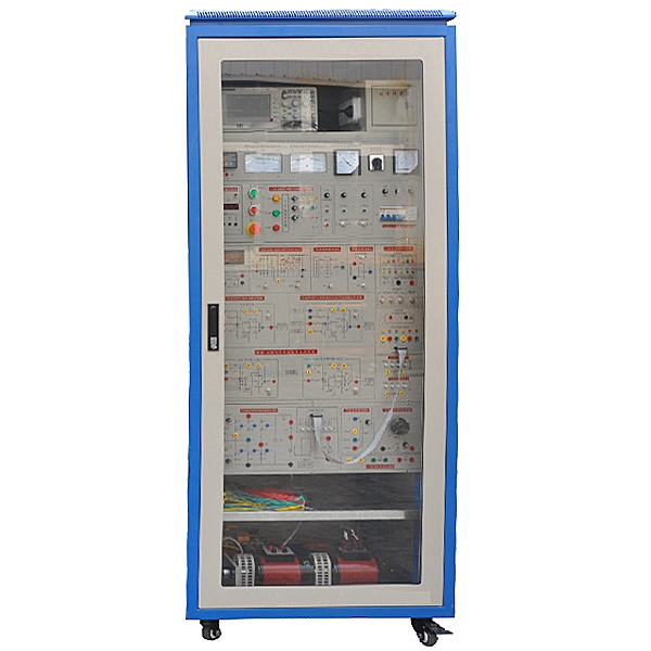
1. Industrial control cabinet
The control cabinet is equipped with a glass door, which is intuitive and clear. The top part is the oscilloscope placement area. The middle part is the control module installation area, power control and instrument area. The instruments are equipped with AC and DC voltmeters, AC and DC ammeters, and digital tachometer (real-time digital display of motor speed and output of analog voltage signals); the lower part is for variable current power. Modules, three-phase synchronous transformers, three-phase current transformers and adjustable resistive loads, etc.
2. Speed regulating unit
Motor guide r*l: fixed motor guide r*l, with good flatness, no stress deformation, fine processing, good concentricity and good interchangeability, which can ensure that the concentricity of the connection between the motor and the motor and the motor and the generator does not exceed ±5 wires. The operation is quiet, and the guide r*l also has a portable handle and vibration-absorbing feet.
DQ09 DC parallel (separate) excited motor: 220V, 1.1A, 185W, 1500rpm.
DQ11 three-phase wound asynchronous motor: 220V, 0.5A, 100W, 1420rpm.
DQ07-1 DC generator: 220V, 1.1A, 240W, 1500rpm.
3. Practical tr*ning control module
Given regulation module
Provides a set of 0~±15V continuously adjustable DC power supply.
Power module
Provides one set of -15V, +15V and +24V DC power supplies.
Voltage single closed-loop regulation module with current cutoff negative feedback
Speed single closed-loop regulation module with current cutoff negative feedback
Voltage and current double closed-loop regulation module
Speed and current double closed-loop adjustment module
Provide speed and current regulators (regulators I and II) for speed control systems. During tr*ning, you can flexibly change the control parameters of the system and observe the effects of different parameters on the system's dynamic performance, steady-state performance stability and response time, etc. The system has no static error and the accuracy is as high as 0.3% or more.
Voltage detection and feedback module (TVD)
Input 0~300V, output 0~10V.
Current detection, feedback and protection module (FBC+FA)
Input 0~2A, output 0~10V.
Speed detection (photoelectric encoder) and speed conversion module (FBS)
Input 0~1500rpm, output 0~10V.
Integrated phase-shifted pulse trigger module
It adopts a three-phase integrated trigger circuit with strong anti-interference ability. The three-phase pulses are evenly spaced and the phase shift smoothness is good. It generates double narrow pulses with a pulse phase shift range of 0~170°. With the thyristor converter module, it can complete the three-phase Practical tr*ning on fully controlled rectification, three-phase AC voltage regulation, etc.
Protection circuit module
It has the functions of m*n circuit overcurrent, short circuit protection, alarm, indication and cutting off the m*n power supply.
Excitation power supply
Provides 220V/0.5A DC power supply.
Thyristor converter
Provide 6 power thyristors.
4. Practical tr*ning projects
Task 1: Debugging of the open-loop system
1. Calibration of power phase sequence
2. Debugging of triggering, driving, detecting and regulating circuits
3. Open loop adjustment (resistive load)
4. Three-phase bridge type fully controlled rectifier circuit
5. Three-phase AC voltage regulating circuit
6. Debugging of protection links (resistive load), setting of overcurrent value and setting of cut-off value
7. Debugging of protection links (motor load), setting of overcurrent value and setting of motor stall and cut-off value
Task 2: Debugging of closed-loop system
1. Adjustment of initial phase angle
2. Determine the polarity and reference value of each feedback quantity
3. Debugging of protection links (resistive load), setting of overcurrent value and setting of cut-off value
4. Debugging of protection links (motor load), setting of overcurrent value and setting of motor stall and cut-off value
5. Voltage feedback coefficient setting
6. Current feedback coefficient setting
7. Speed feedback coefficient tuning
8. Voltage single closed-loop DC speed control system
9. Speed single closed-loop DC speed control system
10. Speed single closed-loop AC speed control system
11. Single closed-loop DC speed regulation system with current cut-off negative feedback speed
12. Single closed-loop AC speed control system with current cutoff negative feedback speed
13. Voltage and current double closed-loop DC speed regulation system
14. Speed and current double closed-loop DC speed control system
15. Speed and current double closed-loop AC speed control system
5. Fault setting function
1. Simulate three-phase synchronization signal phase loss
2. Simulate thyristor trigger circuit f*lure
3. Analog thyristor trigger circuit without offset voltage
4. Simulate the regulator output circuit breakage in the DC speed regulation medium-voltage single closed-loop speed regulation system.
5. The current feedback input terminal of the regulator in the simulated DC speed regulation medium-speed single closed-loop speed regulation system is circuit-opened.
6. Simulate the short circuit of the integral capacitor C of the regulator in the single closed-loop speed control system with medium speed in DC speed control.
7. The speed feedback input terminal of the speed regulator in the double closed-loop speed control system in the simulated DC speed control system is open circuit.
8. The speed feedback input terminal of the speed regulator in the double closed-loop speed control system in the simulated AC speed control system is open circuit.
9. The input terminal of the current regulator in the analog AC and DC double closed-loop speed control system is broken, etc.
Through the arrangement and combination of multiple fault points, more fault situations can be simulated.
 Wechat scan code follow us

24-hour hotline+86 18916464525

Phone18916464525
ADD:Factory 414, District A, No. 6, Chongnan Road, Songjiang Science and Technology Park, Shanghai ICP: Sitemap