Shanghai Daiyu Education Equipment Manufacturing Co., Ltd.
Language:


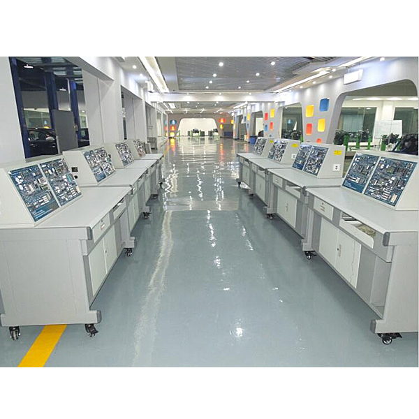


The experimental development system integrates an experimental table and a comprehensive experimental platform. The comprehensive experimental platform adopts an integrated design and can also expand some new experiments through bus sockets.
2. System performance
It is the first in China to apply industrial configuration software to a single-chip microcomputer control system, intuitively and vividly displaying actual automatic control industrial scenarios. The platform is m*nly used for basic application technology and comprehensive application technology of microcontrollers, including microcontroller principles, various control technologies, various data communication technologies, and system design technologies. Provide users with numerous peripheral devices and device interfaces, allowing users to quickly master the principles of microcontrollers and their practical interface technologies, and fully understand and master the applications of various peripheral devices popular in the field of today's microcontrollers. At the same time, students learn the programming and control technology of industrial configuration software (bus control and bit control) to tr*n students to become excellent application-oriented talents to adapt to the social needs of continuous innovation.
3. M*n technical indicators
3.1 Experimental table:
3.1.1Power supply
Power input: two-phase three-wire, AC 220V±10%, 50HZ
Power output: two-phase three-wire AC 220V±10%/50HZ output, used for power supply of computers and measuring instruments.
3.1.2 Device capacity: ≦1KVA
3.1.3 Overall dimensions: reference value 1500×700×1300
3.1.4 Working environment: temperature -10°C~+40°C, relative humidity 85% (25C)
3.1.5 Safety protection: grounding protection, leakage protection (action current <30mA), overload protection
3.1.6 Experimental table body: The experimental table is made of iron and aluminum alloy bench structure, insulated panel, and the desktop is made of fireproof, waterproof, wear-resistant high-density board, with solid structure and beautiful appearance. The lower part of the table is equipped with a computer m*n cabinet, a keyboard rack, and a storage cabinet for placing accessories, tools, information, etc.
4. Det*led hardware technical parameters
4.1 Experimental screen
4.1.1 Monochrome running water lamp module: 8 high-bright green patch 0805 package LED lights
4.1.2 Two-color running water light module: 6 high-brightness in-line LED lights, three colors: red, yellow and green
4.1.3 Two-color LED light module: red and green two-color in-line LED light
4.1.48-bit digital tube module: 2 four-bit common anode digital tubes, 2 74HC595 driver chips.
4.1.51-bit digital tube module: 1 8-segment digital tube, common anode, 0.56 inches
4.1.6 Red and green two-color dot matrix module: three 74HC595 driver chips, one red and green two-color dot matrix display.
4.1.7LCD1602 LCD screen module: standard LCD1602 LCD screen interface, 1 LCD1602 LCD screen with backlight.
4.1.88 independent buttons: 8 independent patch buttons with pull-up resistors
4.1.94X4 matrix keyboard: 4 rows and 4 columns matrix keyboard, a total of 16 SMD buttons, with pull-up resistors.
41.1.10 Five-way joystick: A five-way joystick with five directions: up, down, left, right, and center.
4.1.11 Buzzer module: Passive buzzer
4.1.12DS1302 clock module: DS1302 chip, SOP8 package, module with battery holder on the back.
4.2 Sensor module
4.2.1 Two-channel DS18B20 module: Two-channel DS18B20 temperature sensor interface
4.2.2 Photosensitive sensor module: Integrated LM393 comparator, reference voltage adjustable resistor, analog output interface, digital output interface, analog indicator LED light, and supports photoelectric switching devices such as photodiodes and photoresistors.
4.2.3 Flame sensor module: Integrated LM393 comparator, reference voltage adjustable resistor, analog output interface, digital output interface, analog indicator LED light, supports flame sensor.
4.2.4 Hall sensor module: Integrated LM393 comparator, reference voltage adjustable resistor, analog output interface, digital output interface, analog indicator LED light, supports Hall sensor.
4.3 Electrical control module
4.3.1-channel DC motor interface: ULN2003 driver chip, SOP16 package. One-way speed-adjustable DC motor interface; one-way speed-adjustable and adjustable-direction dual-function motor interface
4.3.22-way stepper motor interface: 2 ULN2003 driver chips, SOP16 package. Two standard 5-wire 4-phase stepper motor interfaces
4.3.32-way relay: ULN2003 driver chip, SOP16 package. Two 5V relays, two 3P terminal blocks.
4.4 Data transmission and storage module
4.4.12-channel serial port: SP3232 chip, SOP16 package, +3.0v-+5V working voltage, one male serial port socket, one female serial port socket, and 4 status indicators.
4.4.2AT24C02 memory module: AT24C02 chip, SOP8 package
4.4.3 Analog input module: 0V-5V input is adjustable, 0R-10K resistance value is adjustable.
4.4.4 Serial to parallel module: 74HC164 chip, SOP14 package
4.4.5 Parallel to serial module: 74HC165 chip, SOP16 package
4.4.6SD card module: standard SD card slot, SPI control, 4-bit transmission mode
4.4.7MAX485 module: MAX485 chip, 1 set of 2P terminal outputs and 1 set of pin outputs.
4.4.8 Infrared emission module: infrared emission diode
4.4.9 Infrared receiving module: HX838 infrared integrated receiving head
4.4.10PCF8591AD/DA module: PCF8591 chip, SOP16W package, 4 analog inputs, 1 analog output, IIC communication.
4.4.11 Latch module: 74HC573 latch chip, compatible with standard CMOS
4.4.12 38 decoder: 74LS138 chip, TTL level
4.4.13 Core board expansion interface: interface socket 29P two rows, IO expansion pin 28P two rows
4.5 Power module
4.5.13V3 power circuit: LM1117-3V3 voltage stabilizing chip
4.5.21V8 power module: LM1117-1V8 voltage stabilizing chip
4.5.3 Power supply lead-out: GND/5V/3V3/1V8 power supply, one set each, each set has 6 leads
4.5.4 Module name: USB interface, miniUSB, Type A female, D+, D-
4.5.5 Self-restoring fuse: breaking current 300ma
4.6 Simulation system
1. Electricity safety and electric shock first *d virtual simulation system (demo and copyright certificate provided): The software uses a virtual screen that combines two-dimensional and three-dimensional to teach students the safety of electricity and first *d methods. The software has single-phase electric shock, two-phase electric shock, and two-phase electric shock first *d. Principles of electric shock, step-over electric shock, low voltage electric shock first *d, high voltage electric shock first *d, artificial respiration rescue method, holding hands breathing rescue method, chest heart compression rescue method, etc., single-phase electric shock rep*r live disconnection, rep*r socket electric shock, outdoor Demonstration of principles such as electric shock. The teaching of low-voltage electric shock and high-voltage electric shock m*nly expl*ns and demonstrates to students how to rescue people who are suffering from low-voltage electric shock or high-voltage electric shock. Artificial respiration rescue method, hand-holding breathing rescue method, and chest cardiac compression rescue method are demonstrated using 3D virtual simulation technology. After rendering and Polish it to make the model look like the real part and look realistic. Through practical tr*ning, students can be educated on the safe use of electricity in the tr*ning room, improve students' safety awareness, and enable students to learn some self-rescue methods, so that students can take cert*n safety measures to protect themselves when encountering danger, and become familiar with various Causes of electrical accidents and practical measures to deal with them to reduce the occurrence of electrical accidents.
2. M*ntenance of electricians, electronic motors and vocational qualification tr*ning assessment simulation software (providing demonstration and copyright certificate): The software content includes common sense of safe electricity use, electrician tools, electrician diagrams, electrician instruments, electrician lighting circuits, motors, transformers, low-voltage electrical appliances, Electric mops, oscilloscopes, low-frequency signal sources, welding processes, SMT technology, electronic product manufacturing processes, troubleshooting, wiring, three-dimensional disassembly and assembly of reducers, disassembly and assembly of shafting mechanisms (including cylindrical gear shafting, bevel gear shafting, worm shaft Department and more than ten experiments) and other modules, schools can select corresponding tr*ning modules for tr*ning according to students' learning progress.
3. Three-meter simulation software (demo and copyright certificate provided): This software is in apk format and can be used on PC or mobile terminals. The functions of this software are: measurement of resistance and measurement of AC voltage ( Measuring the transformer, if the multimeter burns out when measuring the transformer, black smoke will appear and the multimeter can be reset), transistor polarity judgment, DC voltage measurement (the light will turn on when the ammeter is turned on), DC current measurement, and capacitance is good. Bad judgment. This software can drag the red and black pen tips at will. When the two pen tips are dragged and positioned on the object to be measured, a red circle will be displayed. If the positioning is not accurate, no red circle will be displayed, and when incorrect operations are performed (such as the wrong range selected, If the measured data is wrong, etc.), the meter pointer will be unresponsive, prompting errors and re-measurement, etc. This multimeter can select AC voltage range, DC voltage range, resistance range, current range, resistance adjustment to 0, and can enlarge the display data. Clearly view the measured data size. Students can learn the correct use of multimeters through this software.
4. Teacher teaching design system (providing demonstration and copyright certificate): This system is in apk format and can be used on PC or mobile. This system can set faults manually or automatically. This system has passed The green box in the circuit diagram selects manual setting of fault points (up to 39 fault points can be set), or the system can automatically set one random fault point, two random fault points, three random fault points, and four random fault points automatically. Fault point setting, five random fault point settings. This system has toolbox, component library, magnifying glass, circuit diagram and other functions. You can choose a multimeter for detection through the toolbox, select appropriate components through the component library, and you can clearly see through the magnifying glass. Understand the various components and circuits. This system allows students to understand the working principle and circuit structure of the motor star-delta start control circuit through the setting of faults in the motor star-delta start control circuit and various investigations.
5. Experimental projects that can be realized
5.1 Experiment box bottom plate function
1) Can realize marquee and running water lantern experiments
2) Color running lights and traffic light experiments can be realized
3) Can realize red and green color display.
4) It can realize electronic clock display, digital tube multi-digit display, 74HC595 driver and other experiments.
5) Can realize 1-digit digital tube display experiment
6) Can do two-color dot matrix screen display experiments, scrolling, static display of characters, Chinese symbols, etc.
7) LCD1602 liquid crystal screen display experiment can be realized, which can display characters, numbers, etc.
8) Experiments such as button control and external interrupts can be realized.
9) Matrix keyboard experiments can be realized and can be used for control, teaching experiments, etc.
10) Can be used as a game control stick to achieve independent button functions.
11) Can realize music playback, alarm prompts, etc.
12) Electronic watch and perpetual calendar experiments can be realized.
5.2 Sensor module functions
1) Temperature measurement can be achieved.
2) Photoelectric switch experiments can be realized.
3) Experiments such as fire alarm and flame detection can be realized.
4) Experiments such as speed measurement and electromagnetic detection can be realized.
5.3 Electrical control module functions
1) Driving experiments of DC motor speed and direction adjustment can be realized.
2) It can realize the driving experiment of stepper motor speed adjustment, direction adjustment and angle adjustment.
3) Relay control experiments can be realized.
5.4 Data transmission and storage module functions
1) Serial communication and TTL to RS-232 experiments can be realized.
2) External storage and IIC bus learning can be realized
3) Can be used as analog input for experiments such as AD conversion.
4) Serial to parallel experiments can be realized and IO can be expanded.
5) Experiments of converting parallel data to serial can be realized
6) It can realize SD card reading and writing and file system learning experiments.
7) With multiple sets of 485 modules, 485 communication experiments can be carried out
8) Can emit infrared signals with different carrier frequencies.
9) Infrared receiving and decoding experiments can be realized.
10) Can realize AD/DA conversion.
11) Can realize 8-bit data latch experiment, and can be used as driver and buffer module for CPU and peripheral modules
12) Can be expanded with IO and learn decoding experiments.
5.5 Power module function
1) Can output +3.3V voltage
2) Can output +1.8V voltage
3) Can be used as the power pin for external modules
4) Baseboard power supply and USB communication interface.
5) Infrared receiving and decoding experiments can be realized.
6. Experimental platform configuration table
|
serial number |
name |
illustrate |
quantity |
|
1 |
Microcontroller experimental bench (standard configuration) |
It includes upper and lower stages, power supply, 51CPU microcontroller core system, 51 microcontroller simulator, and experimental module circuit. |
1 |
|
3 |
A complete set of accessories such as experimental wires and communication lines |
1 |
|
|
4 |
Complete set of experimental instructions |
1 |
|
|
5 |
Complete set of debugging download software and experimental routines |
1 |
 Wechat scan code follow us

24-hour hotline+86 18916464525

Phone18916464525
ADD:Factory 414, District A, No. 6, Chongnan Road, Songjiang Science and Technology Park, Shanghai ICP: Sitemap