Shanghai Daiyu Education Equipment Manufacturing Co., Ltd.
Language:


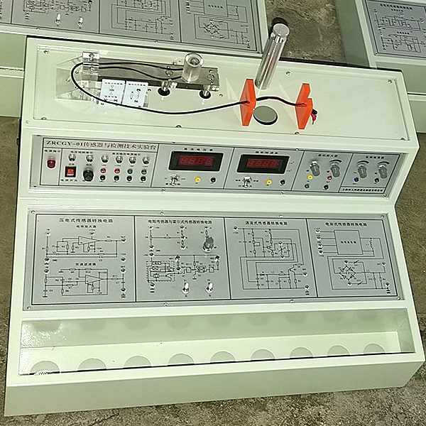


2. Technical indicators of detection and conversion (sensor) technology experiment instrument:
(1) Display instrument requirements:
1. The experiment box provides four sets of DC regulated power supplies: ±5V, ±15V; 1.2~12V adjustable, with short-circuit protection function.
2. Low-frequency signal generator: 1Hz-30Hz output continuously adjustable, Vp-p value 10V, maximum output current 0.5A.
3. Differential amplifier: pass frequency band 0-10KHz, can be connected into a DC amplifier with in-phase, reverse-phase or differential structure and g*n of 1-150 times.
4. Digital voltmeter: three-and-a-half-digit display, range ±2V, ±20V, input impedance 100KΩ, accuracy 1%.
5. Digital frequency/tachometer: composed of four digital tubes and two light-emitting tubes, input impedance 100KΩ, accuracy 1%. The frequency measurement range is 1-9999 Hz, and the rotation speed measurement range is 1-9999Pem.
(2) Three sources:
1. Heating source: 6V, 12V AC power supply heating, temperature control range 0~100℃.
2. Rotation source: 0-12V DC power supply, adjustable speed range 0~2400 rpm.
3. Vibration source: vibration frequency 1-30Hz, resonance frequency around 12Hz.
(3) Data acquisition card and processing software:
Data acquisition work uses 12-bit AD conversion, RS232 interface, resolution from 1/22048, sampling period 1m-100ms, sampling speed is selectable, either single sampling or continuous sampling. The processing software provided has a good computer interface and can be used for selecting and editing experimental items, data collection, analysis and comparison of characteristic curves, file access, printing, etc.
(4) M*n technical parameters:
1. Input power: AC220V±5% 50±1Hz
2. Rated current: ≤5A
3. DC power supply: ±5V ±15V
4. Voltage stabilization coefficient: ±1%
5. Voltage ripple: ≤10mV
6. Nonlinear error: ≤5%
7. Measurement accuracy: ≤1%
8. Power consumption: 100VA
9. Output current: 1A
10. Relative temperature: -5℃~40℃
11. Relative humidity: <85% (25℃)
12. Experiment box specifications: about 610×500×400mm
(5) Sensor types and technical indicators:
|
serial number |
Experimental module |
Sensor name |
Measuring range |
Accuracy |
|
1 |
Resistive and Hall sensor modules |
Resistive sensor |
±2mm |
±1.5% |
|
2 |
Hall sensor |
≥ 2mm |
0.2% |
|
|
3 |
Capacitive sensor module |
capacitive sensor |
±5mm |
±3% |
|
4 |
Inductive sensor module |
Inductive sensor |
±5mm |
±2% |
|
5 |
Photoelectric sensor module |
Photoelectric sensor |
0-2400 rpm |
≤ 1.5% |
|
6 |
Eddy current sensor module |
Eddy current sensor |
≥1mm |
±3% |
|
7 |
Eddy current speed sensor |
0-2400 rpm |
≤ 1.5% |
|
|
8 |
Temperature sensor module |
Temperature sensor |
0-100℃ |
±2% |
|
9 |
Magnetoelectric sensor |
0.5V/m |
||
|
10 |
Magnetoelectric speed sensor |
0-2400 rpm |
≤ 1.5% |
|
|
11 |
Piezoelectric acceleration sensor module |
Piezoelectric acceleration sensor |
1-30Hz |
±2%/s |
|
12 |
Fiber optic sensor module |
Fiber optic sensor |
≥1.5mm |
±1.5% |
|
13 |
Piezoresistive pressure sensor module |
Pressure Sensor |
0-50kpa |
±2% |
|
14 |
Differential amplifier conversion circuit |
gas sensor |
50-200ppm |
|
|
15 |
Low frequency oscillator conversion circuit |
Humidity sensor |
10-95%RH |
±5% |
|
16 |
Hall speed sensor |
0-2400 rpm |
±1.5% |
|
|
17 |
Speed sensor |
0-2400 rpm |
≤ 1.5% |
|
|
18 |
Thermocouple and thermal resistance sensor experiment instrument |
0-100℃ |
±3% |
|
|
19 |
K type thermocouple |
0-100℃ |
±3% |
(6) Features of the detection and conversion (sensor) technology experimental bench :
1. The sensor shell is made of imported transparent organic glass and hard polychloride, and various precision sensors are installed inside.
2. Each sensor is independent, and the schematic diagram and wiring port are printed on the sensor, making it quick and convenient for students to do experiments, and teachers can bring it to class for lectures.
3. The sensor conversion circuit board adopts a modular structure, and the conversion schematic diagram and wiring port are printed on the module.
4. Simulation system
1. Electricity safety and electric shock first *d virtual simulation system (demo and copyright certificate provided): The software uses a virtual screen that combines two-dimensional and three-dimensional to teach students the safety of electricity and first *d methods. The software has single-phase electric shock, two-phase electric shock, and two-phase electric shock first *d. Principles of electric shock, step-over electric shock, low voltage electric shock first *d, high voltage electric shock first *d, artificial respiration rescue method, holding hands breathing rescue method, chest heart compression rescue method, etc., single-phase electric shock rep*r live disconnection, rep*r socket electric shock, outdoor Demonstration of principles such as electric shock. The teaching of low-voltage electric shock and high-voltage electric shock m*nly expl*ns and demonstrates to students how to rescue people who are suffering from low-voltage electric shock or high-voltage electric shock. Artificial respiration rescue method, hand-holding breathing rescue method, and chest cardiac compression rescue method are demonstrated using 3D virtual simulation technology. After rendering and Polish it to make the model look like the real part and look realistic. Through practical tr*ning, students can be educated on the safe use of electricity in the tr*ning room, improve students' safety awareness, and enable students to learn some self-rescue methods, so that students can take cert*n safety measures to protect themselves when encountering danger, and become familiar with various Causes of electrical accidents and practical measures to deal with them to reduce the occurrence of electrical accidents.
2. M*ntenance of electricians, electronic motors and vocational qualification tr*ning assessment simulation software (providing demonstration and copyright certificate): The software content includes common sense of safe electricity use, electrician tools, electrician diagrams, electrician instruments, electrician lighting circuits, motors, transformers, low-voltage electrical appliances, Electric mops, oscilloscopes, low-frequency signal sources, welding processes, SMT technology, electronic product manufacturing processes, troubleshooting, wiring, three-dimensional disassembly and assembly of reducers, disassembly and assembly of shafting mechanisms (including cylindrical gear shafting, bevel gear shafting, worm shaft Department and more than ten experiments) and other modules, schools can select corresponding tr*ning modules for tr*ning according to students' learning progress.
3. Three-meter simulation software (demo and copyright certificate provided): This software is in apk format and can be used on PC or mobile terminals. The functions of this software are: measurement of resistance and measurement of AC voltage ( Measuring the transformer, if the multimeter burns out when measuring the transformer, black smoke will appear and the multimeter can be reset), transistor polarity judgment, DC voltage measurement (the light will turn on when the ammeter is turned on), DC current measurement, and capacitance is good. Bad judgment. This software can drag the red and black pen tips at will. When the two pen tips are dragged and positioned on the object to be measured, a red circle will be displayed. If the positioning is not accurate, no red circle will be displayed, and when incorrect operations are performed (such as the wrong range selected, If the measured data is wrong, etc.), the meter pointer will be unresponsive, prompting errors and re-measurement, etc. This multimeter can select AC voltage range, DC voltage range, resistance range, current range, resistance adjustment to 0, and can enlarge the display data. Clearly view the measured data size. Students can learn the correct use of multimeters through this software.
4. Teacher teaching design system (providing demonstration and copyright certificate): This system is in apk format and can be used on PC or mobile. This system can set faults manually or automatically. This system has passed The green box in the circuit diagram selects manual setting of fault points (up to 39 fault points can be set), or the system can automatically set one random fault point, two random fault points, three random fault points, and four random fault points automatically. Fault point setting, five random fault point settings. This system has toolbox, component library, magnifying glass, circuit diagram and other functions. You can choose a multimeter for detection through the toolbox, select appropriate components through the component library, and you can clearly see through the magnifying glass. Understand the various components and circuits. This system allows students to understand the working principle and circuit structure of the motor star-delta start control circuit through the setting of faults in the motor star-delta start control circuit and various investigations.
(7) Sensor equipment list:
|
serial number |
Device name |
unit |
quantity |
|
1 |
Resistive Hall sensor conversion circuit |
piece |
1 |
|
2 |
Capacitive sensor conversion circuit |
piece |
1 |
|
3 |
Inductive sensor conversion circuit |
piece |
1 |
|
4 |
Photoelectric sensor conversion circuit |
piece |
1 |
|
5 |
Eddy current sensor conversion circuit |
piece |
1 |
|
6 |
Temperature sensor conversion circuit |
piece |
1 |
|
7 |
Piezoelectric acceleration sensor conversion circuit |
piece |
1 |
|
8 |
Fiber optic sensor conversion circuit |
piece |
1 |
|
9 |
Pressure sensor conversion circuit |
piece |
1 |
|
10 |
Differential amplifier conversion circuit |
piece |
1 |
|
11 |
Low frequency oscillator conversion circuit |
piece |
1 |
|
12 |
Resistive sensor |
indivual |
1 |
|
13 |
capacitive sensor |
indivual |
1 |
|
14 |
Hall sensor |
indivual |
1 |
|
15 |
Inductive sensor |
indivual |
1 |
|
16 |
Photoelectric sensor |
indivual |
1 |
|
17 |
Eddy current sensor |
indivual |
1 |
|
18 |
Eddy current speed sensor |
indivual |
1 |
|
19 |
Temperature sensor |
indivual |
1 |
|
20 |
Magnetoelectric sensor |
indivual |
1 |
|
twenty one |
Magnetoelectric speed sensor |
indivual |
1 |
|
twenty two |
Piezoelectric acceleration sensor |
indivual |
1 |
|
twenty three |
Fiber optic sensor |
indivual |
1 |
|
twenty four |
Pressure Sensor |
indivual |
1 |
|
25 |
gas sensor |
indivual |
1 |
|
26 |
Humidity sensor |
indivual |
1 |
|
27 |
Hall speed sensor |
indivual |
1 |
|
28 |
Speed sensor |
indivual |
1 |
|
29 |
Thermocouple and thermal resistance sensor experiment instrument |
indivual |
1 |
|
30 |
E type thermocouple sensor |
indivual |
1 |
|
31 |
K type thermocouple |
indivual |
1 |
|
32 |
Micrometer |
Bundle |
1 |
|
33 |
pressure gauge |
Only |
1 |
|
34 |
rubber *r bag |
indivual |
1 |
|
35 |
tee pipe |
indivual |
1 |
|
36 |
One iron sheet, one copper sheet, and one aluminum sheet |
indivual |
3 |
|
37 |
Thermometer 0-100℃ |
branch |
1 |
|
38 |
Φ8×4 magnet |
piece |
1 |
|
39 |
Ultrasonic reflective baffle |
piece |
1 |
|
40 |
Instructions Experiment Guide |
Book |
1 |
|
41 |
Connecting wires |
root |
15 |
|
42 |
Microcomputer cable |
root |
1 |
|
43 |
Data acquisition and processing software |
plate |
1 |
(8) Experimental projects: (Those marked with ※ are thought experiments)
Experiment 1 Single-arm bridge performance experiment of resistive sensor
Experiment 2 Half-bridge performance experiment of resistive sensor
Experiment 3 Full-bridge performance experiment of resistive sensors
Experiment 4 Comparative experiment of single-arm, half-bridge and full-bridge resistive sensors
Experiment 5 Vibration experiment of resistive sensor*
Experiment 6 Electronic scale experiment with resistive sensor*
Experiment 7 Variable area capacitive sensor characteristics experiment
Experiment 8 Differential Capacitive Sensor Characteristics Experiment
Experiment 9 Vibration experiment of capacitive sensor*
Experiment 10 Electronic scale experiment with capacitive sensor*
Experiment 11 Characteristic experiment of differential transformer
Experiment 12 Characteristics experiment of self-induction differential transformer
Experiment 13 Vibration experiment of differential transformer*
Experiment 14 Electronic scale experiment of differential transformer*
Experiment 15: Speed measurement experiment of photoelectric sensor
Experiment 16: Rotation direction measurement experiment of photoelectric sensor
Experiment 17 Proximity Hall sensor experiment
Experiment 18: Speed measurement experiment of Hall sensor
Experiment 19 Displacement Characteristics Experiment of Eddy Current Sensor
Experiment 20: Experiment on the influence of the material of the measured object on the characteristics of the eddy current sensor
Experiment 21 Vibration experiment of eddy current sensor*
Experiment 22 Speed measurement experiment of eddy current sensor
Experiment 23 Temperature sensor and temperature control experiment (AD590)
Experiment 24: Characteristics experiment of magnetoelectric sensors
Experiment 25 Speed measurement experiment of magnetoelectric sensor
Experiment 26 Application Experiment of Magnetoelectric Sensor*
Experiment 27 Characteristics experiment of piezoelectric acceleration sensor
Experiment 28 Displacement Characteristics Experiment of Optical Fiber Sensor
Experiment 29 Vibration experiment of optical fiber sensor
Experiment 30: Speed measurement experiment of optical fiber sensor
Experiment 31 Characteristics experiment of piezoresistive pressure sensor
Experiment 32: Differential pressure measurement experiment of piezoresistive pressure sensor*
Experiment 33: Principle experiment of gas sensor
Experiment 34: Humidity sensor principle experiment
Experiment 35 Temperature control experiment of K-type thermocouple
Hot-selling product: Electrician tr*ning bench
 Wechat scan code follow us

24-hour hotline+86 18916464525

Phone18916464525
ADD:Factory 414, District A, No. 6, Chongnan Road, Songjiang Science and Technology Park, Shanghai ICP: Sitemap