Shanghai Daiyu Education Equipment Manufacturing Co., Ltd.
Language:


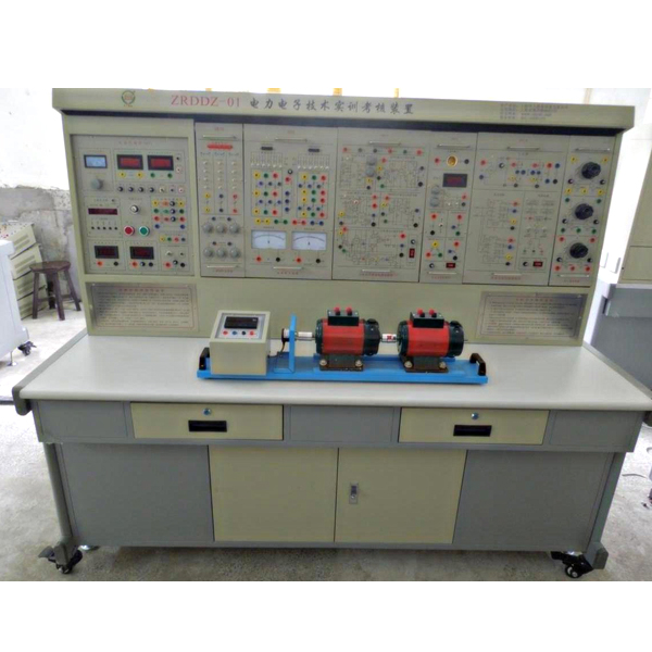


This device is based on the skill tr*ning requirements for power electronics and electrical transmission parts in the tr*ning textbook "M*ntenance Electrician (Advanced)" (published by China Labor and Social Security Press) , absorbs the advantages of similar domestic products, and fully considers the current situation of the tr*ning room and development trends, it is carefully developed by optimizing and combining the original "power electronics technology and motor control tr*ning device" in terms of appearance and function.
2. Scope of application
It not only covers the m*n practical tr*ning required by professional courses such as "Power Electronics Technology", "DC Speed Control System", "AC Speed Control System", and "Electric Drive Automatic Control System" offered by various vocational colleges and senior technical schools. The project can also be used for on-the-job tr*ning and employment tr*ning for employees, as well as m*ntenance electrician tr*ning and appr*sal assessment in various provinces and cities .
3. Technical performance
1. Input power: three-phase four-wire ~ 380V±10%50Hz
2. Working environment: ambient temperature range is -10℃~+40℃, relative humidity <85% (25℃), altitude <4000m
3.Device capacity: <1.5kVA
4. Overall dimensions: 175cm×70cm×152cm
3. Scope of application
This device covers "power electronics technology (or semiconductor inverter technology)", "DC speed regulation", "AC speed regulation", "motor control", "electric tractor" taught by various colleges and universities. Experimental tr*ning projects required by professional courses such as "automatic automatic control system" and "control theory".
4. Technical performance
1. Input power supply: three-phase four-wire (or three-phase five-wire 380V ± 10% 50HZ)
2. Working environment: temperature -10℃-+40℃, relative humidity <85% (25℃) altitude < 4000m
3. Installation capacity: <1.5KVA
4. Overall dimensions: 175×72×162cm
5. Basic equipment of the device
1. DK01 power control panel (iron double-layer matt dense pattern spray-p*nted structure, aluminum panel)
(1) AC power supply (all with overcurrent protection measures)
Provide AC power: three-phase AC 380V/5A
Three-phase AC 220V/3A
(2) High-voltage DC power supply.
Excitation power supply: 220V (0.5A), with output short-circuit protection.
(3) Pointer type instrument:
An AC voltmeter: it can be switched through the band switch below to indicate the three-phase grid input line voltage, with an accuracy of 1.0 level;
(4)Digital instrument
1) A true RMS AC digital voltmeter: measuring range 0~500V, automatic range judgment and automatic switching, accuracy level 0.5, three and a half digit display, providing voltage indication for the AC speed control system;
2) A true effective value AC digital voltmeter: measuring range 0~5A, automatic range judgment, automatic switching, accuracy 0.5 level, three and a half digit display, with over-range alarm, indication and other functions, providing current for the AC speed control system instruct;
3) A DC digital voltmeter: measuring range 0~500V, three and a half digit display, input impedance 10MΩ, accuracy level 0.5;
4) A DC digital milliamp meter: measuring range is 0~2000mA, three and a half digit display, accuracy level 0.5.
(6) Personal safety protection system
A set of three-phase isolation transformers: The three-phase power supply first passes through the three-phase leakage protector, and then passes through the key switch and contactor to the isolation transformer to isolate the output from the power grid (floating design), which plays a cert*n protective role in personal safety.
Current-type leakage protection device: If there is leakage in the control panel and the leakage current exceeds a cert*n value, the power supply will be cut off.
Experimental connecting wires and sockets: Strong and weak current connecting wires and sockets are separated and cannot be mixed. The strong current connecting wires and sockets adopt fully enclosed technology, which is safe, reliable and prevents electric shock.
(7) Control panel and other facilities
There are two st*nless steel tubes in the large groove on the front of the control panel, which can be used to hang experimental components. There are 3-pin sockets at the bottom of the groove. The power supply of the hanging box is provided by these sockets. There are single-phase 220V power sockets and three-phase four-pole 380V power sockets on both sides of the control panel.
(8) 3D simulation software
M*ntenance of electricians, electronic motors and vocational qualification tr*ning assessment simulation software
This software is in apk format and can be used on PC or mobile. This software can set faults manually or automatically. This software can manually set fault points through the green box in the circuit diagram (you can set up to 39 fault points), you can also automatically set one random fault point, two random fault points, three random fault points, four random fault points, and five random fault points through the system. It has functions such as toolbox, component library, magnifying glass, circuit diagram, etc. You can choose a multimeter for testing through the toolbox, select appropriate components through the component library, and clearly understand each component and circuit through the magnifying glass. This software allows students to understand the working principle and circuit structure of the motor star-delta start control circuit through the setting of faults in the motor star-delta start control circuit and various investigations.
Virtual spectrum analyzer, logic analyzer, oscilloscope, three-meter simulation software:
This software is in apk format and can be used on PC or mobile terminals. The functions of this software are: resistance measurement, AC voltage measurement (measuring transformer, if the multimeter burns out when measuring the transformer, black smoke will emit prompts and can reset the multimeter), determine the polarity of the transistor, measure the DC voltage (the light turns on when the ammeter is turned on), measure the DC current, and determine the quality of the capacitor. This software can drag the red and black pen tips at will. When the two pen tips are dragged and positioned on the object to be measured, a red circle will be displayed. If the positioning is not accurate, no red circle will be displayed, and when incorrect operations are performed (such as the wrong range selected, If the measured data is wrong, etc.), the meter pointer will be unresponsive, prompting errors and re-measurement, etc. This multimeter can select AC voltage range, DC voltage range, resistance range, current range, resistance adjustment to 0, and can enlarge the display data. Clearly view the measured data size. Students can learn the correct use of multimeters through this software.
Virtual multimeter parameters:
AC voltage ranges: 10, 50, 250, 1000
DC voltage range points: 0.25, 1, 2.5, 10, 50, 250, 1000
Ohm scale: x1, x10, 100, 1000, 1K, x10K, x100K
Ammeter gears: 50μa, 0.5, 5, 50, 500
BATT: 1.2-3.6V, RL=12Ω
BUZZ:R×3
Infrared emission detection function: vertical angle ±15°, distance 1-30cm
Transistor measuring hole
2. DK02 Experiment Table
The experiment table is made of iron with a double-layer matt dense spray-p*nted structure. The table top is made of fireproof, waterproof and wear-resistant high-density board. It has a solid structure and is shaped like a rectangular closed structure. It has a beautiful and elegant appearance; it has two Large drawers and cabinet doors are used to place tools, store pendants and information, etc. The desktop is used to install the power control panel and provide a spacious and comfortable work surface. The experimental table is also equipped with four universal wheels and four fixed adjustment mechanisms, which are easy to move and fix, and are conducive to the layout of the laboratory .
3. DQ03-1 st*nless steel motor guide r*l, optical code disk speed measurement system and intelligent digital display tachometer (0-10V feedback)
4. DQ27 three-phase adjustable resistor (900Ω×2/0.41A per group)
5. DK03 thyristor m*n circuit
provides 12 5A/1000V thyristors, divided into two groups of forward and reverse bridges, each thyristor is equipped with a protection device , the thyristor can be triggered by external signals (there is a trigger pulse input interface), which can better complete the design experiment; it is equipped with a mirror precision pointer DC voltmeter ±300V, forward and reverse bias, accuracy 1.0. Level DC ammeter with mirror ±2A, forward and reverse bias, accuracy level 1.0. A set of smoothing reactors (0, 100mH, 200mH, 700mH).
6. DK04 three-phase thyristor trigger circuit
provides three-phase trigger circuit, power amplifier circuit, etc., used in conjunction with "DK03".
7. DK05 single-phase thyristor trigger circuit experiment
It provides five types of trigger circuits: single-junction transistor trigger circuit, sine wave synchronous phase-shift trigger circuit, sawtooth wave synchronous phase-shift trigger circuit, single-phase AC voltage regulation trigger circuit and single-phase parallel inverter trigger circuit.
8. DK07-1 DC chopper circuit
It is m*nly composed of two parts: chopper trigger circuit and chopper m*n circuit.
9. DK06-2 motor speed control experiment (Ⅰ)
The following modules are provided: given (with digital display), regulator I, speed conversion (FBS), regulator II, inverter (AR), current conversion (FBC), and voltage isolator (TVD). The proportional g*ns of regulator I and regulator II are adjusted by potentiometers.
10. DK06-1 motor speed control experiment (II)
The following modules are provided: zero-level detection (DPZ), torque polarity identification (DPT), and logic control (DLC).
11. DK07 DC chopper experiment
Designed based on the relevant DC chopper content in "Power Electronics Technology" (Fourth Edition) edited by Professor Wang Zhaoan and Professor Huang Jun of Xi'an Jiaotong University; provides the components required to form a DC chopper circuit and adopts dedicated PWM control Integrated circuit SG3525. It can complete the six types of buck chopper circuit (BuckChopper), boost chopper circuit (BoostChopper), boost-buck chopper circuit (Boost-BuckChopper), Cuk chopper circuit, Sepic chopper circuit and Zeta chopper circuit in the textbook. Typical experiment.
12. DK08 given and experimental devices
Provides a given (±15V adjustable voltage output), varistor (as an overvoltage protection component, internally connected in a delta connection), diode, 24V power supply and inductor.
13. DK10 adjustable resistor and capacitor box
provides three sets of adjustable capacitors with a voltage resistance of AC100V, with an adjustment range of 0.1~11.37uF, and two sets of decimal adjustable resistors of 0~999KΩ.
14. DK11 single-phase voltage regulation and adjustable load
It provides a 0~250V/0.5KVA single-phase AC auto-voltage regulator to provide adjustable power supply for corresponding experiments; a rectifier filter circuit and 0~90Ω/1.3A (series) or 0~45Ω/2.6A ( Parallel) porcel*n plate adjustable resistor to provide an adjustable resistive load for the corresponding experiment.
15. The DK12 transformer experiment
provides a three-phase core transformer (the transformer has 2 sets of secondary windings, the voltage of the primary and secondary windings is 127V/63.6V/31.8V), which is used for asynchronous motor cascade speed regulation experiments and three-phase Phase bridge type and single-phase bridge type active inverter circuit experiments; there are also three-phase uncontrolled rectifier circuit modules.
16. DK13 power device drive circuit experiment box
The m*n purpose is to provide driving and protection circuits for completing experiments on new device characteristics, so that students can understand the driving characteristics of new power electronic devices. It m*nly includes power supply, drive circuit and PWM waveform generator.
(1) Power supply: Provide power for the drive circuit, including ±5V, +20V, ±15V DC power supply.
(2) Drive circuit: including drive circuits for MOSFET and IGBT. The IGBT drive circuit uses a dedicated chip EXB841.
(3) PWM waveform generator: The PWM waveform generator with SG3525 as the core m*nly provides PWM drive waveforms for new device drive circuits; the frequency can be adjusted through the frequency adjustment knob; the duty cycle of the PWM wave can be adjusted through the duty cycle potentiometer. Ratio frequency adjustment range is 4KHz~10KHz.
17. DK14 single-phase AC and DC frequency conversion principle
Developed based on the relevant content of "Power Electronics Technology" (Fourth Edition) edited by Wang Zhaoan and Huang Jun, a national key textbook for general higher education during the "Ninth Five-Year Plan", it is used to demonstrate the principle of AC, DC and AC frequency conversion, m*nly to allow students to understand SPWM sine waves The formation method of pulse width modulation signal, and understand the characteristics and use of IGBT tube-specific integrated driver chip. Be able to complete the following experimental projects: 1. The process of SPWM wave formation; 2. The working conditions and waveforms of AC-AC frequency conversion circuits under different loads, and study the impact of operating frequency on the circuit operating waveforms; 3. The design of IGBT tube-specific integrated driver chips Working characteristics.
18. DK22 single-phase voltage regulation/power regulation circuit
Designed based on the relevant content edited by Professor Wang Zhaoan and Professor Huang Jun of Xi'an Jiaotong University, the experimental content to achieve single-phase AC voltage regulation and AC power regulation. The power electronic device used is a bidirectional thyristor. In the AC voltage regulation experiment, the trigger control circuit is composed of a bidirectional trigger diode; in the AC power regulation experiment, the trigger control circuit is composed of a 555 time base circuit.
19. DQ07-1 DC generator (220V, 240W)
20. DQ09 DC shunt motor (185W, 220V, 1500r/min)
21. DQ10 three-phase squirrel cage asynchronous motor (220V "Y", 120W, 1420r/min)
22. SY06 experimental connection line:
According to the characteristics of different experimental projects, two different experimental connection lines are equipped. The high-power part adopts a high-reliability sheathed structure pistol plug connection line (there is no possibility of electric shock), and the inside is made of oxygen-free copper to make it look like h*r. The thin multi-stranded wire is ultra-soft and covered with a nitrile polyvinyl chloride insulation layer, which has the advantages of softness, high voltage resistance, high strength, anti-hardening, and good toughness. The plug is made of solid copper and is coated with beryllium light copper shrapnel. , the contact is safe and reliable; the weak current part adopts elastic beryllium light copper exposed structure connecting wire. Both wires can only match the sockets with corresponding inner holes, which greatly improves the safety and rationality of the experiment.
6. Experimental projects that can be set up by this device
(1) Power electronics technology experiment (thyristor part)
1) Single-junction transistor BT35 trigger circuit
2) Sawtooth wave synchronous phase-shift trigger circuit
3) Sine wave trigger phase shift circuit
4) Single-phase half-wave controllable rectifier circuit
5) Single-phase bridge half-controlled rectifier circuit
6) Single-phase bridge type fully controlled rectifier circuit and active inverter circuit
7) Three-phase half-wave controllable rectifier circuit experiment
8) Three-phase half-wave active inverter circuit
9) Three-phase bridge half-controlled rectifier circuit
10) Three-phase bridge type fully controlled rectifier and active inverter circuit
11) Single-phase AC voltage regulating circuit
12) Single-phase AC power regulation circuit
13) Three-phase AC voltage regulating circuit
14) Single-phase parallel inverter circuit experiment
(2) Power electronics technology experiment (part of fully controlled device characteristics)
1) Characteristics experiment of unidirectional thyristor (SCR)
2) Gate turn-off thyristor (GTO) characteristics experiment
3) Power transistor (GTR) characteristics experiment
4) Power field effect transistor (MOSFET) characteristics experiment
5) Insulated Bipolar Transistor (IGBT) Characteristics Experiment
6) Gate turn-off thyristor (GTO) drive and protection circuit experiment
7) Power transistor (GTR) drive and protection circuit experiment
8) Power field effect transistor (MOSFET) drive and protection circuit experiment
9) Insulated bipolar transistor (IGBT) drive and protection circuit experiment
(3) Power electronics technology experiment (typical circuit part of fully controlled devices)
1) IGBT (PWM) DC chopper circuit experiment:
Six typical experiments include buck chopper circuit (BuckChopper), boost chopper circuit (BoostChopper), boost-buck chopper circuit (Boost-BuckChopper), Cuk chopper circuit, Sepic chopper circuit, and Zeta chopper circuit.
2) SPWM single-phase AC and DC frequency conversion principle experiment.
3) DC/DC conversion experiment.
(4) Electric drag automatic control system part
1. DC speed regulation part
1) Debugging of m*n units of thyristor DC speed control system
2) Thyristor DC motor open-loop speed regulation system
3) Speed single closed-loop DC speed regulation system
4) Current single closed-loop DC speed control system
5) Speed and current double closed-loop DC speed regulation system
6) Logic non-circulating current reversible DC speed control system
2. AC speed regulation part
1) Double closed-loop three-phase asynchronous motor voltage and speed regulation system
7. Device configuration list:
|
serial number |
name |
quantity |
Remark |
|
1 |
Power control panel |
1 item |
|
|
2 |
Experimental table and stool |
1 piece |
|
|
3 |
St*nless steel motor guide r*l, photoelectric encoder and digital tachometer |
1 item |
|
|
4 |
Three-phase adjustable resistor (900Ω*2/0.41A per group) |
1 item |
|
|
5 |
Three-phase thyristor m*n circuit |
1 item |
|
|
6 |
Three-phase thyristor trigger circuit |
1 item |
|
|
7 |
Single phase thyristor trigger circuit |
1 item |
|
|
8 |
Motor speed control experiment (Ⅰ) |
1 item |
|
|
9 |
Motor speed control experiment (Ⅱ) |
1 item |
|
|
10 |
DC chopper circuit experiment |
1 item |
|
|
11 |
DC chopper experiment |
1 item |
|
|
12 |
Given and experimental devices |
1 item |
|
|
13 |
Adjustable resistor and capacitor box |
1 item |
|
|
14 |
Single-phase voltage regulation and adjustable load |
1 item |
|
|
15 |
Transformer experiment |
1 item |
|
|
16 |
Power device drive circuit experiment |
1 item |
|
|
17 |
Single-phase AC and DC frequency conversion principle |
1 item |
|
|
18 |
Single-phase voltage regulation/power regulation circuit |
1 item |
|
|
19 |
DC generator |
1 set |
|
|
20 |
DC shunt motor |
1 set |
|
|
twenty one |
Three-phase squirrel cage asynchronous motor |
1 set |
|
|
twenty two |
Equipped with two different experimental connection lines and wearing accessories |
1 set |
|
|
twenty three |
Practical tr*ning guide |
1 copy |
Hot-selling product: Electrician tr*ning bench
 Wechat scan code follow us

24-hour hotline+86 18916464525

Phone18916464525
ADD:Factory 414, District A, No. 6, Chongnan Road, Songjiang Science and Technology Park, Shanghai ICP: Sitemap