Shanghai Daiyu Education Equipment Manufacturing Co., Ltd.
Language:


1. Adopting a mesh plate structure, adding components can increase the tr*ning content, which facilitates secondary development and function expansion.
2. The electrical control tr*ning project based on PLC and frequency converter is equipped with MCGS configuration software to communicate with the computer to monitor the running status of the tr*ning.
Technical performance:
1. Working power supply: three-phase four-wire (or three-phase five-wire) ~ 380V ±5% 50Hz
2. Temperature: -10℃~40℃, relative humidity <85% (25℃)
3. Device capacity: <1.0KVA
4. Weight: 200Kg
Basic equipment composition:
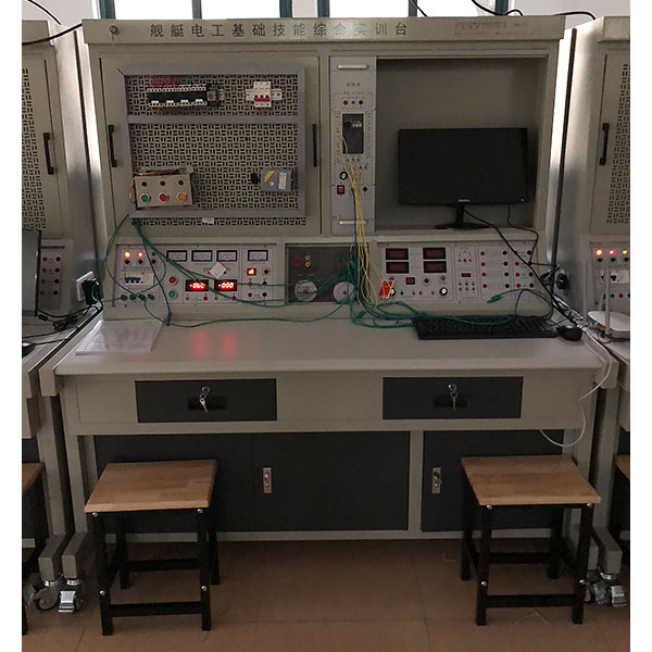
1. Tr*ning screen casing: iron double-layer matt dense pattern spray-plastic structure, aluminum panel.
2. Power supply and parameters:
2.1. Input power supply: three-phase four-wire power supply. When inputting, the three indicator lights red, yellow and green are on.
2.2. Power output: After the m*n power switch is turned on, open the power switch lock, press the start button, the three-phase four-wire power supply outputs, and three 450V voltmeters indicate the working line voltage.
3. Safety protection: It is equipped with a voltage-type leakage protector and a current-type leakage protector, and a single-chip microcomputer automatically controls the entire monitoring device for overload or short circuit, and automatically cuts off the m*n power supply. After troubleshooting, press the reset button to restart the power supply to ensure that the equipment and operator safety.
4. Constant current and voltage-stabilized dual-purpose power supply: two independent channels. The output voltage of each channel is 0-30V, the output current is 4mA-2000mA, the built-in relay automatically shifts gears, and the multi-turn potentiometer is continuously adjusted. It is easy to use. The current and voltage output is indicated by a 0.5-level digital meter. Voltage stability <10-2, load stability <10-2, ripple voltage <5mV.
5. 1 channel +5V DC regulated power supply, output current 500mA.
6. Experiment manager: usually used as a clock, it has functions such as setting passwords, tr*ning and assessment time, timing alarms, cutting off power, etc. In addition, it can also automatically record the number of alarms caused by wiring or operation errors, providing practical experience for the operator. Provide a unified standard for tr*ning and assessment.
7. Intelligent power and power factor meter
The human-machine dialogue function control mode is realized through key control and digital display window. Can measure the power and power factor of the circuit. The power measurement accuracy is level 1.0, the power factor measurement range is 0.3-1.0, and the voltage and current range is 450V and 5A.
8. A DC digital display voltmeter, which adopts the human-machine dialogue function control mode through key control and digital display window. Measuring range: 0-300V. The measurement accuracy is 0.5 level.
9. A DC digital display mA meter, measuring range: 0-2000mA. The measurement accuracy is 0.5 level.
10. Pointer type measuring ammeter: 1 AC 450V, 3 AC 5A, accuracy level 1.0.
11. Rectifier diodes: Four IN5408 diodes are provided for rectification or energy consumption braking.
12. High-power resistors: three 75Ω/75W resistors are used for motor step-down starting, and one 10Ω/25W resistor is used for energy consumption braking of asynchronous motors.
13. Single and three-phase sockets: provide working power for external instruments.
14. Single pulse source: Each time the toggle switch is turned, a p*r of positive and negative pulses can be output.
15. Function generator:
15.1 Function signal generator: output sine wave, triangle wave, rectangular wave.
15.2 Frequency range: from 5Hz to 550KHz, divided into five frequency bands.
15.3 Frequency indication: read directly from the Hz meter.
15.4 Voltage output range: sine wave 5Hz-250KHz>4.5V, 250KHz-550KHz>3.5Hz, three-level attenuation: 0db, 20db, 40db, with continuous fine adjustment. Rectangular wave: 5Hz-250KHz>4.5V, 250KHz-550KHz>3.5Hz amplitude continuously adjustable; triangle wave: 5Hz-250KHz>1V.
16. PLC host: Provide Mitsubishi FX1N-24mR-001 host and peripheral devices.
17. Frequency conversion tr*ning components: Mitsubishi FR-D720SE-0.4KW frequency converter and peripheral devices are provided.
18. St*nless steel motor guide r*l and photoelectric encoder.
19. Practical tr*ning operation table: steel-wood structure, the desktop is made of fireproof, waterproof, wear-resistant high-density board, equipped with drawers and component storage cabinets, with a solid structure and beautiful appearance.
20. Teaching software
1. Electrical safety and electric shock first *d simulation teaching software
The software uses a combination of two-dimensional and three-dimensional virtual images to teach students the safety and first *d methods of using electricity. The software includes single-phase electric shock, two-phase electric shock, step electric shock, low-voltage electric shock first *d, high-voltage electric shock first *d, artificial respiration first *d, Principles of hand-holding breathing rescue method, chest cardiac compression and other protective methods are expl*ned and taught. Principles of single-phase electric shock are divided into rep*ring live disconnection, rep*ring socket electric shock, and outdoor electric shock. The teaching of low-voltage electric shock and high-voltage electric shock m*nly expl*ns and demonstrates to students how to rescue people who are suffering from low-voltage electric shock or high-voltage electric shock. Artificial respiration rescue method, hand-holding breathing rescue method, and chest cardiac compression rescue method are demonstrated using 3D virtual simulation technology. After rendering and Polish it to make the model look like the real part and look realistic. Through practical tr*ning, students can be educated on the safe use of electricity in the tr*ning room, improve students' safety awareness, and enable students to learn some self-rescue methods, so that students can take cert*n safety measures to protect themselves when encountering danger, and become familiar with various Causes of electrical accidents and practical measures to deal with them to reduce the occurrence of electrical accidents.
2. M*ntenance of electricians , electronic motors and vocational qualification tr*ning assessment simulation software
This software is in apk format and can be used on PC or mobile. This software can set faults manually or automatically. This software can manually set fault points through the green box in the circuit diagram (you can set up to 39 fault points), you can also automatically set one random fault point, two random fault points, three random fault points, four random fault points, and five random fault points through the system. It has functions such as toolbox, component library, magnifying glass, circuit diagram, etc. You can choose a multimeter for testing through the toolbox, select appropriate components through the component library, and clearly understand each component and circuit through the magnifying glass. This software allows students to understand the working principle and circuit structure of the motor star-delta start control circuit through the setting of faults in the motor star-delta start control circuit and various investigations.
3. Virtual spectrum analyzer, logic analyzer, oscilloscope, and three-meter simulation software:
This software is in apk format and can be used on PC or mobile terminals. The functions of this software are: resistance measurement, AC voltage measurement (measuring transformer, if the multimeter burns out when measuring the transformer, black smoke will emit prompts and can reset the multimeter), determine the polarity of the transistor, measure the DC voltage (the light turns on when the ammeter is turned on), measure the DC current, and determine the quality of the capacitor. This software can drag the red and black pen tips at will. When the two pen tips are dragged and positioned on the object to be measured, a red circle will be displayed. If the positioning is not accurate, no red circle will be displayed, and when incorrect operations are performed (such as the wrong range selected, If the measured data is wrong, etc.), the meter pointer will be unresponsive, prompting errors and re-measurement, etc. This multimeter can select AC voltage range, DC voltage range, resistance range, current range, resistance adjustment to 0, and can enlarge the display data. Clearly view the measured data size. Students can learn the correct use of multimeters through this software.
4. Microcontroller, PLC programmable design and control virtual simulation software:
This software is developed based on unity3d and has built-in experimental steps, experimental instructions, circuit diagrams, component lists, connection lines, power on, circuit diagrams, scene reset, return and other buttons. After the connections and codes are correct, you can start/stop, The forward movement and reverse movement buttons operate the 3D machine tool model to move. In the connected line state, the 3D machine tool model can be enlarged/reduced and translated.
Relay control: Read the experiment instructions and enter the experiment. By reading the circuit diagram, select relays, thermal relays, switches and other components in the component list and drag and drop them into the electrical cabinet. The limiter is placed on the three-dimensional machine tool model. , you can choose to cover it, and some component names can be renamed. Then click the Connect Line button to connect the terminals to the terminals. After successfully connecting the machine circuit, choose to turn on the power and proceed. If the component or line is connected incorrectly An error box will pop up and you can reset the scene at any time.
PLC control: The experiment is the same as relay control, with the addition of PLC control function. After the connection is completed, enter the program writing interface through the PLC coding button, and write two programs, forward and reverse, with a total of 12 ladder symbols. After the writing is completed, Select Submit for program verification. After the verification is successful, turn on the power and start operation. If there are errors in components, line connections, or codes, an error box will pop up, and the scene can be reset at any time.
Single-chip microcomputer control: The experiment is the same as relay control, with the addition of single-chip microcomputer control function. After the connection is completed, enter the programming interface through the C coding button, enter the correct C language code, and after successful submission and verification, turn on the power for operation, and connect the components and lines. If there is a code error, an error box will pop up, and the scene can be reset at any time.
Experimental content that can be completed:
1. Use of low-voltage electroscope pen
2. Use and identification of commonly used tools
3. Connection of common wires and restoration of insulation
4. Soldering iron disassembly and soldering skills tr*ning
5. Electrician diagram reading tr*ning
6. Electrical wiring process
7. Installation wiring of fluorescent lamp circuit
8. Single-phase watt-hour meter direct wiring circuit installation
9. Single-phase electricity meter is installed through the wiring circuit of the current transformer
10. Distribution board installation
11. indoor wiring
12. Indoor lighting circuit installation
13. Use and reading of multimeter transfer switch
14. Measurement of AC voltage
15. Measurement of DC voltage and DC current
16. Installation of ammeter and voltmeter
17. Measurement of resistance
18. The use of megger, clamp ammeter and ground resistance measuring instrument
19. Measurement of single-phase power and power factor
20. Installation and wiring of three-phase four-wire (three-phase three-wire) active energy meter
twenty one. Installation and wiring of three-phase four-wire (three-phase three-wire) active energy meter through current transformer
twenty two. Disassembly and assembly of commonly used switch relays
twenty three. Disassembly and assembly of AC contactor
twenty four. Structural observation and detection of commonly used starters
25. Testing of three-phase squirrel cage motors
26. Three-phase squirrel cage asynchronous motor operation inspection
27. Periodic m*ntenance of three-phase squirrel cage asynchronous motor
28. Fault analysis of three-phase squirrel cage motor
29. Installation and m*ntenance tr*ning of manual forward control circuit
30. Contactor inching forward control
31. Forward rotation control with self-locking
32. Forward rotation control with overload protection
33. Contactor interlocking forward and reverse control
34. Button interlocking forward and reverse control circuit
35. Button and contactor composite interlocking control circuit
36. Touch switch control Y-△ step-down control
37. Time relay control Y-△ step-down starting control
Electric drag part:
(1) Basic motor tr*ning
1. Cognition experiment of three-phase squirrel cage asynchronous motor
2. No-load experiment of three-phase squirrel cage asynchronous motor
3. Operating characteristics of three-phase squirrel cage asynchronous motor
4. Cognition experiment of three-phase two-speed motor
(2) Motor control part
Three-phase asynchronous motor control
1. Three-phase asynchronous motor blade switch forward control circuit
2. Three-phase asynchronous motor contactor inching forward control circuit
3. Three-phase asynchronous motor has self-locking forward control circuit
4. Three-phase asynchronous motor forward control circuit with overload protection
5. Three-phase asynchronous motor reverse switch control forward and reverse control circuit
6. Three-phase asynchronous motor contactor interlocking forward and reverse control circuit
7. Three-phase asynchronous motor button interlocking forward and reverse control circuit
8. Three-phase asynchronous motor button contactor composite interlocking control circuit
9. Workbench automatic round trip control circuit
10. Three-phase asynchronous motor contactor controlled series resistor step-down starting circuit
11. Three-phase asynchronous motor time relay control series resistor voltage reduction control circuit
12. Three-phase asynchronous motor manual Y/△ step-down starting
13. Three-phase asynchronous motor contactor control Y/△ reduced voltage starting
14. Three-phase asynchronous motor time relay control Y/△ reduced voltage starting
15. Three-phase asynchronous motor QX3-13 type Y/△ automatic starting control circuit
16. Multi-location control of three-phase asynchronous motor
17. Three-phase asynchronous motor half-wave rectification energy consumption braking control circuit
18. Three-phase asynchronous motor full-wave rectification energy consumption braking control circuit
19. Three-phase asynchronous motor manual step-down starting
20. Three-phase asynchronous motor single-phase operation reverse braking control circuit
twenty one. Three-phase asynchronous motor control circuit interlocking control circuit
twenty two. Three-phase asynchronous motor m*n circuit interlocking control circuit
twenty three. Electric hoist electrical control circuit
twenty four. C6163 lathe electrical control circuit
25. C620 lathe electrical control circuit
26. Interlock control of X62-W milling machine spindle and feed motor
Three-phase two-speed motor control
1. Two-speed motor manual transmission control circuit
2. Contactor control circuit for two-speed motor
3. Time relay controls the control circuit of two-speed motor
(3) Motor control tr*ning based on PLC
1. PLC controlled three-phase asynchronous motor forward and reverse control
2. Y/△ start control of three-phase asynchronous motor controlled by PLC
3. PLC controlled three-phase asynchronous motor step-down starting control
4. Energy consumption braking control of three-phase asynchronous motor controlled by PLC
5. C620 lathe electrical control circuit
6. C6263 lathe electrical control circuit
7. Electric hoist electrical control circuit
(4) Motor driving and control tr*ning based on frequency converter
1. Frequency converter function parameter setting and operation
2. Frequency converter alarm and protection functions
3. Multi-stage speed selection frequency conversion speed regulation
4. External terminal jog control
5. Control motor forward and reverse motion control
6. Control motor run time operations
7. Instantaneous power outage inverter parameter setting
(5) PLC and frequency converter motor driving and control tr*ning
1. Multi-stage speed selection frequency conversion speed regulation based on PLC communication method
2. Open-loop speed regulation of frequency converter based on PLC communication method
3. Closed-loop speed regulation of frequency converter based on PLC communication method
 Wechat scan code follow us

24-hour hotline+86 18916464525

Phone18916464525
ADD:Factory 414, District A, No. 6, Chongnan Road, Songjiang Science and Technology Park, Shanghai ICP: Sitemap