Shanghai Daiyu Education Equipment Manufacturing Co., Ltd.
Language:


1. Product Overview: The
Electronic Design Automation (EDA) tr*ning platform is a high-end experimental development platform based on Altera's CycloneIII/IV/V series FPGA. The unique GUI human-machine operation interface adopts a flexible design of system baseboard + core board + expansion board, and is equipped with a variety of expansion modules for users to choose and configure.
The Electronic Design Automation (EDA) tr*ning platform adopts the design method of system base board + core board + expansion board, and forms a development platform with different functions by selecting different core boards and expansion boards. It can meet the performance needs of users to the maximum extent. The modular design allows users to have a clear understanding of the system design.
2. M*n technical indicators:
1. Input voltage: single-phase three-wire ~ 220V ± 10% 50Hz
2. Device capacity: <1kVA
3. Working environment: temperature -10℃ ~ +40℃ relative humidity <85% (25℃)
4 , Device capacity: <500VA
5. Dimensions: The size of a single tr*ning platform is 1.6m×0.7m×1.15m.
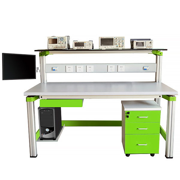
3. Product structure:
The device consists of instrument rack, power control box, experimental table, EDA experimental system, mobile low cabinet, student stool, etc. The experimental device bracket and experimental table can be combined and disassembled. The bracket is integrated with the table leg and has an aluminum alloy structure.
(1) Instrument rack: The instrument rack is placed on the top of the tr*ning platform. It is composed of cross-sectional dimensions: 70mm × 70mm, high-performance surface oxidized aluminum profiles, double-sided plastic sprayed steel plates and one-time aluminum die-cast frame connection components (non-welded process) , beautiful appearance, solid and durable structure. The bottom of the instrument rack is equipped with a hidden flat lighting LED lamp. The light source is concentrated, soft and bright, and the appearance is beautiful.
(2) Power supply control box: The power supply control box has an aluminum profile structure and is embedded with multiple sets of AC 220V instrument working power sockets, and is equipped with an independent leakage protection switch. The power supply control box is placed under the instrument rack, making it safe and convenient to use instruments and meters. And equipped with LED light control switch.
(3) Tr*ning table structure:
The specifications of the tr*ning table are 1400 (length) * 700 (width) * 1150 (height). It is equipped with a keyboard support and a drawer. There is a computer chassis support on the right side of the lower part of the table. The m*n structure of the experimental table is all made of high-performance surface-oxidized aluminum profiles and one-time aluminum die-cast frame connecting components. The connecting components adopt die-casting molding process (non-welding process), and are machined, shot blasted, sandblasted, surface electrostatic sprayed, and installed. Convenient and fast, users can DIY the assembly by themselves. The table column adopts industrial aluminum profile molding process, with surface oxidation treatment. Cross-sectional size: 70mm×70mm, with grooves on four sides, the groove width is about 8mm, and the end is equipped with injection molding matching plastic plugs. The desktop is made of 25mm E1 grade melamine decorative panel. There is a support frame under the desktop panel with a bearing capacity of not less than 300kg. Equipped with a storage cabinet to store components and tools. The bottom of the storage cabinet has 4 high-strength universal brakeable PU casters for easy movement. The overall tr*ning device is simple but not simple, high-end and in line with modern product aesthetics and development trends.
Two legs with a cross-sectional size of 70mm x 70mm at the back of the experimental table extend upward and form a solid bracket (non-welding process) with the one-time aluminum die-cast frame connection component. Together with the instrument rack and power control box, they form a complete tr*ning screen.
(4) 1 storage cabinet: Equipped with a storage cabinet to store tr*ning modules and tools. The bottom of the storage cabinet has 4 high-strength universal brakeable PU casters for easy movement.
(5) 2 back ch*rs: The back ch*rs are made of strong thick steel pipe supports, which are strong and durable, the structure is ergonomic, not tiring after sitting for a long time, and the linen surface has good texture.
(6) Experimental equipment: 1 set of EDA experimental system, two people can complete the experimental project together. Technical indicators:
The EDA/SOPC system comprehensive development platform is a high-end experimental development based on Altera's latest CycloneIII/IV/V series FPGA platform. The unique GUI human-machine operation interface adopts a flexible design of system baseboard + core board + expansion board, and is equipped with a variety of expansion modules for users to choose and configure.
The development platform adopts the design method of system base board + core board + expansion board, and forms a development platform with different functions by selecting different core boards and expansion boards. It can meet the performance needs of users to the maximum extent. The modular design allows users to have a clear understanding of the system design.
Development platform hardware resources
Ø FPGA-4C10 FPGA core board
The core board adopts a 6-layer high-precision PCB design, making the system operation more stable and reliable.
The m*n chip uses Altera's CycloneIV series FPGA EP4CE10F17C8N, with up to 1 million gate circuits.
The FPGA configuration chip uses EPCS16, with a capacity of up to 16M BIT and a number of erasing and writing times of up to tens of thousands.
Provides JTAG programming mode.
After the core board is connected to the system board, a USB-Blaster cable is installed on the board; only one USB cable is needed to download the program to the core board.
A 50M high-speed and stable clock source.
A system reset circuit.
The system power management module can provide power outputs of various voltages such as +5V, +3.3V, +2.5V, 1.2V, etc. for system use.
16M*16BIT SDRAM all the way.
The system provides four reset buttons with LED lights.
The core board provides more than 130 IOs that are not reused with other resources of the core board for users to use for secondary development.
Ø EDA/SOPC system board
comes standard with 854*480 24-bit TFT color serial LCD display. Users can replace displays with different specifications.
It comes standard with a capacitive touch screen.
1 analog signal generator module, which can provide signal waveforms such as sine wave, triangle wave, square wave, etc. with adjustable frequency and amplitude.
1 digital clock output module, which can provide digital pulse signals from 24M to 1HZ.
1 8-bit high-speed parallel ADC interface module with speed up to 40 Msps.
One 8-bit high-speed parallel DAC interface module with speeds up to 33 Msps.
1 serial A/D conversion interface.
1 serial D/A conversion interface.
1 VGA interface module.
1 UART serial communication module.
1 USB to serial device interface.
1 Ethernet10M/100M high-speed interface module.
1 SD card interface module and
2 PS2 interface modules, which can be connected to a keyboard or mouse.
1 E2PROM with I2C interface, model number is AT24C08N.
1 audio CODEC module (speaker and buzzer optional, volume adjustable).
1 RTC real-time clock chip with clock power-down protection and online battery charging functions.
12 toggle switch and 12 key switch inputs.
12 illuminated LED displays.
1 eight-digit seven-segment code tube display module.
2-digit static digital tube display module.
16x16 matrix led dot matrix display module.
The 4X4 matrix key input module has
a voltage-controlled DC motor and a four-phase stepper motor module.
1 digital temperature sensing and 1 Hall sensor module.
HH-EXT high-speed interface module.
Multiple power outputs (all with overcurrent and overvoltage protection).
4. Experimental project
EDA experiment and electronic design competition experiment content:
Simple QUARTUSII example design
Design of Gray code encoder
Adding counter with asynchronous clearing and enable
Design of eight-bit seven-segment digital tube display circuit Design of
CNC
frequency divider Design of mixed input circuit for graphics and language. Design
of variable-step addition and subtraction counter.
Design of four-bit parallel multiplier
. Design of four-bit full adder.
Design of controllable pulse generator. Design of
basic flip-flop.
Design of matrix keyboard display circuit
16* 16-dot matrix display experiment
DC motor speed measurement experiment
Stepper motor drive control
Traffic light experiment
Design of DDS signal generator
Electronic music design experiment
PLL phase-locked loop IP design experiment
PS2 interface keyboard display experiment
Design of VGA color bar signal generator
Seven people Voting machine design experiment
Four-person answering machine design experiment Design of
positive and negative pulse width modulation signal generator Design of
digital frequency meter Design of
multi-functional digital clock
Design of digital stopwatch Design
of taxi meter
Design of digital lock
Design of PS2 mouse encoding
SPI Design of serial AD/DA converter
1602 LCD experiment
...
Qsys 32-bit processor example experiment
***Simple Qsys system design
PIO IP core - running water lamp experiment
SDRAM IP core system design
SPI Flash programming experiment
PIO input - switch Signal reading experiment
PIO IP core-interrupt
Design of timer based on Timer IP core
Matrix keyboard and digital tube display experiment
UART serial port communication experiment
EEPROM read and write experiment based on IIC
SDRAM read and write operation experiment
1602 LCD display experiment
RTC real-time clock Experiment
Serial AD/DA-SPI core
Signal generator-SPI core
1-WIRE digital thermometer design
Dot matrix character display experiment
SD card reading experiment
5. Configuration table
| serial number | Name | illustrate | quantity |
| 1 | instrument stand | 1 set | |
| 2 | Power control box | 1 set | |
| 3 | Experiment table | 1 piece | |
| 4 | Mobile low cabinet | 1 | |
| 5 | student ch*r | 2 pictures | |
| 6 | EDA experimental system | Table I | 1 set |
| 7 | tool | 1 p*r of needle nose pliers, 1 p*r of tweezers, 1 p*r of diagonal pliers | 1 set |
| 8 | computer | Prepared by user | 1 set |
Table I
| Device name | EDA/SOPC system comprehensive development platform | |
| core chip | EP4CE10F17C8N | |
| Operating Voltage | ~220v±10%, 50Hz±1Hz | |
| Dimensions (mm) | 420 x 290 x 130 | |
| Weight(kg) | <5 | |
| Software version | QuartusII 13.0,NiosII SBT for Eclipse 13.0, ModelSim 13.0 | |
| routine language | Provides two versions of Verilog and VHDL routines for users to use | |
| Accessory list | Serial cable × 1 | USB cable × 1 |
| Network cable × 1 | Power cable × 1 | |
| Experiment Instructions × 3 | Development DVD Kit × 1 | |
 Wechat scan code follow us

24-hour hotline+86 18916464525

Phone18916464525
ADD:Factory 414, District A, No. 6, Chongnan Road, Songjiang Science and Technology Park, Shanghai ICP: Sitemap