Shanghai Daiyu Education Equipment Manufacturing Co., Ltd.
Language:


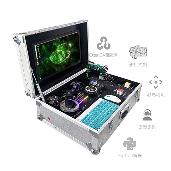


The system includes a six-degree-of-freedom robotic arm , a wide dynamic AI vision camera, a Jetson Nano edge processing terminal 17.3-inch edge computing display unit, a machine vision scenario application resource package, and can simulate typical artificial intelligence application scenarios to realize artificial intelligence application technology teaching experiments.
The teaching platform system is pre-installed with the Ubuntu 18.04 operating system, and all environment code library files have been installed and can be used immediately after booting. Based on a multi-dimensional learning and practice platform, you can gradually progress from the basic GPIO expansion to the sensor experiment project, and then enter OpenCVPyTorch, ROS system, machine kinematics, AI machine vision, AI speech recognition and hearing, so as to learn AI artificial intelligence development.
The algorithm source code provided (including face detection, license plate recognition, garbage classification, and target detection) is compatible with Caffe/TensorFlow/MXNet tr*ning models and APIs, which can enable students to have a better understanding of the process and processing methods of machine vision, become familiar with related algorithms, understand actual application scenarios, and get close to engineering applications.
1. Jetson Nano edge computing platform
NVIDIA Jetson Nano is a small but powerful computer that allows you to run multiple neural networks, object detection, segmentation, and speech processing applications in parallel. Jetson Nano is equipped with a quad-core cortex-A57 processor, a 128-core Maxwell GPU, and 4GB LPDDR memory, which brings enough AI computing power, provides 472GFLOP computing power, and supports a series of popular Al frameworks and algorithms, such as TensorFlow, Pytorch.caffe/caffe2, Keras, MXNET, etc.
2. Machine Vision (Robot Arm)
The visual robotic arm uses Jetson nano as the m*n control, Open Source CV as the image processing library, the m*nstream Jupyter Lab as the development tool, and Python3 as the m*n programming language. The camera and the robotic arm are designed in an integrated manner. The "hand-eye integration" visual recognition makes the robotic arm more flexible. It can not only realize color recognition, tracking and grasping, but also human feature recognition interaction, and even garbage classification model tr*ning and garbage sorting; through the RO5 robot control system, the complex motion control of the 6-DOF serial bus servo is simplified.
1080P camera: Photosensitive element size: 1/237”; Maximum effective resolution: 1928*1088; Data format: YUY2/MJPG; Pixel size: 3.0μm*3.0μm; Wide dynamic range: 96DB; Automatic control: saturation, contrast, sharpness, white balance, exposure.
Robotic arm: Cortex-M3 core processor control board, free-degree-of-freedom desktop robot arm, high-power serial bus intelligent servo, arm span 350mm, load ≥300g, with gripper, anodized aluminum alloy body, m*nly used for industrial robot arm control. Supports python programming, can flexibly and accurately adjust the angle and position of each joint; supports PC host computer, mobile phone APP, USB game controller control;
3. Speech Recognition - Microphone Array
The microphone array is designed based on the MSM261S4030H0 digital microphone chip. The module has high sound recognition sensitivity and signal-to-noise ratio, and can be used in sound source positioning, speech recognition, beamforming and other demanding occasions.
1. RISC-V Dual Core 64bit, with core, m*n frequency 400MHz, 8M Byte, built-in speech recognition microphone array (8mics), network model: support YOLOv3 \ Mobilenetv2 \ TinyYOLOv2, support TensorFlow/Keras/Darknet/Caffe and other m*nstream frameworks
2. Microphone: 6+1 MSM261S4030H0 array (sound pressure level: 140 dB SPL, sensitivity: -26, signal-to-noise ratio: 57dB, THD<1%, clock frequency: 1.0-4.0MHz normal mode, 150-800kHz low power mode)
2. Lighting: 12 LEDs cascaded via dual signal lines (color and brightness adjustable)
3. Support sound source positioning, voice navigation, voice interaction, and offline voice recognition.
4. LiDAR
Compared with traditional technology, infrared laser equipment can achieve multi-touch on ultra-large screens, with faster response, higher precision, and stronger resistance to ambient light. As a core sensor, laser radar can quickly obt*n environmental contour information. When used with SLAMWARE, it can help robots build maps autonomously, plan paths in real time, and automatically avoid obstacles. Application areas: smart sweepers and household robots.
Measuring radius: 12 meters, measuring frequency: 8000 times/second, scanning frequency: 5.5HZ, 360-degree scanning distance measurement
Engineering Application
1. Basic application of computer vision and motion control of robotic arms
(1) Visual positioning: Place any object in the field of view, segment it (frame it) in the image, and output the coordinates of the center point;
(2) Color recognition and sorting: Multiple colors are mixed and placed in the field of vision, one for each color, and the control arm selects a cert*n color and places it on one side;
(3) Color recognition and stacking: Multiple colors are mixed and placed in the field of vision, such as two colors, two of each color, and the arm is controlled to grab a cert*n color and stack it, or multiple colors are stacked separately;
(4) Shape recognition and sorting: Multiple shapes are mixed and placed in the field of view. Each shape is selected separately, and the control arm selects a cert*n shape and places it on one side.
(5) Shape recognition and stacking: Multiple shapes are mixed and placed in the field of view, such as two shapes, two of each shape, and the arm is controlled to grasp a cert*n shape and stack it, or to stack multiple shapes separately;
(6) Single shape target sorting by size: Place three objects of the same shape in the field of view, and control the arm to place them in order from large to small;
(7) Multiple shapes are stacked by shape and size at the same time: three shapes, each with three different sizes of objects, are placed in the field of view, and the arm is controlled to stack them in the order of different shapes from large to small (i.e., three stacks, all from large to small);
(8) Garbage classification: Patterns of different objects are pasted on the target, such as cabbage, glass bottles marked as toxic substances, and cardboard boxes, and mixed in the field of view. Through configuration, the robot arm is controlled to classify the garbage into kitchen waste, hazardous waste, and recyclable waste.
(9) Gesture interaction: For example, if you extend 1, 2, 3, or 4 fingers, the robotic arm will move up, down, left, and right respectively. If you extend 5 fingers, it will draw a circle.
(10) Target tracking: The operator holds a small ball, and the robotic arm recognizes the ball (shape or color) and moves with the ball;
(11) OCR optical character recognition and sorting: characters are pasted on the target and placed in random order (it can be required that the characters must face the same direction, but the order is random). The robotic arm uses visual recognition to place them in the specified position in the order of 123456.
2. Computer vision and applications such as face recognition and license plate recognition
(1) Face recognition: Enter the face in advance and recognize the new face. If the recognition is successful, the person's information will pop up. If the recognition is not successful, it will prompt that the person is not in the system.
(2) Face access control: After the face is recognized, the access control system is turned on and the green indicator light is on. If the face cannot be recognized, the yellow indicator light is on, indicating that there is no information about the person.
(3) Personnel intrusion warning: Same as above. If the same face is recognized more than 3 times in a row and is not in the system, the red light will turn on and the buzzer will sound an alarm;
(4) License plate recognition: Enter the license plate in advance and recognize the new license plate. If the recognition is successful, the owner's information will pop up and the green indicator light will light up. If the recognition is not successful, the yellow light will light up and it will indicate that the vehicle is not in the system.
(5) Vehicle intrusion warning: Same as above. If the same license plate is recognized more than 3 times in a row and is not in the system, the red light will turn on and the buzzer will sound an alarm.
(6) Moving target recognition and tracking: Use real-time video recognition to identify one or more people in the field of view, frame them, mark the number of people identified, and track them as they move;
3. Voice recognition and smart home system
(1) Intelligent access control: pre-mark the voice, configure the voice command and access control system control algorithm, and realize the action of automatically opening the access control system when the command "open the door" is issued;
(2) Intelligent lighting control: Pre-mark the voice, configure the voice command and lighting control algorithm, and realize the action of automatically turning on the light when issuing the command "turn on the light";
(3) Intelligent fan control: Pre-mark the voice, configure the voice command and fan control algorithm, and realize the action of automatically turning on the fan when the command "turn on the fan" is issued;
(4) Intelligent temperature and humidity detection: Pre-mark the voice, and by configuring the voice command and temperature and humidity sensor control algorithm, it is possible to implement actions such as issuing a command such as "What is the temperature today?" The sensor automatically turns on and displays the current ambient temperature and humidity on the screen.
Siemens PLC simulation tr*ning software includes basic instructions, application instructions, and sequential control instructions
1. Basic instructions: motor start and stop control, motor forward and reverse control, motor cycle forward and reverse, reversible operation reverse braking, three-speed motor control, star-angle step-down starting control, digital tube lighting control, traffic light control, constant pressure water supply system control.
1. Motor start and stop control includes: tr*ning requirements, tr*ning devices, device layout, I/O allocation, T-type diagram, circuit connection, power-on operation, etc.
(1) Tr*ning requirements: Presentation in the form of text and pictures. Summarize the m*n knowledge points to understand that the m*n learning content of this module includes the programming method of two-site control circuits, learning to design PLC peripheral circuits for actual control, and learning to design simple ladder diagrams for actual control requirements of branch offices.
(2) Tr*ning devices: List all the devices used in the motor start-stop control unit, including three-phase asynchronous motor, PLC, AC contactor, three-phase circuit breaker, fuse, thermal relay, start button, and stop button.
(3) Device layout: Place the simulated devices in the device library in the corresponding positions in the simulated power distribution cabinet to tr*n students to understand the devices and circuits. There must be corresponding symbols on the circuit. If the device is dragged incorrectly, the device will not be dragged up and a corresponding sound will be displayed.
(4) I/O allocation: The software cont*ns I/O allocation addresses and circuit diagrams. When you click the mouse on the allocation address resource, a corresponding picture of the object will be displayed to help students better understand the device model and circuit diagram.
(5) T-graph: A T-graph with missing symbols and the corresponding symbols are given. Students use the mouse to drag the symbols onto the T-graph based on what they have learned. If the symbols are correct, they rem*n on the T-graph; otherwise, they disappear.
(6) Circuit connection:
The flashing line in the schematic diagram is the circuit that should be connected currently. Click one of the two contacts that connect this line with the mouse, then drag the mouse to find the other contact and click it. If it is correct, the connection line will appear. If it is incorrect, the line will disappear. Only when the connection is correct can the next line be connected. If you encounter difficulties in wiring, you can click the "Answer" button. After clicking, the completed wiring diagram will appear. You can refer to the diagram to complete your operation. Click the "Answer" button ag*n and the answer will disappear.
You can wire freely and refer to the circuit diagram for free wiring. If you don’t know how, you can click on the prompt. Click on any wiring hotspot with the mouse and the hotspot at the other end will flash.
(7) Power-on operation: This is achieved through simulation tr*ning. After power is turned on, you can press the corresponding switch according to the operating steps to visually observe the operation of the circuit. At the same time, the sound effects that simulate the real scene are used to achieve the simulation effect.
Supporting Experiment Content
Python basic part experiment
Chapter 1 Python
Chapter 2 Development Environment Construction and Usage
Chapter 3 Python Basics
3.1 Python Syntax
3.2 Python Indentation
3.3 Python Comments
3.4 Python variables
3.5 Python introduces foreign *d
3.6 Python basic data types
3.7 Python Common Operators
Chapter 4 Python Branching and Looping
4.1 Python branching and looping
4.2 Python Conditional Expressions and Assertions
4.3 Python loop statements
Chapter 5 Advanced Python
5.1 Python Lists
5.2 Python Tuples
5.3 Python Strings
5.4 Python Sequences
5.5 Python Dictionary
5.6 Python Collections
Chapter 6 Python Functions
6.1 Creating and calling Python functions
6.2 Python function parameters and return values
6.3 Variables in Python Functions
6.4 Python Functional Programming
6.5 Python Recursion
Chapter 7 Python Storage
7.1 Python Files
7.2 Python File System (OS)
Chapter 8 Python Exception Handling
8.1 Python try-except statement
8.2 Python try-finally statement
8.3 Python r*se statement
Chapter 9 Python Classes and Objects
9.1 Python Objects
9.2 Python inheritance
9.3 Python Multiple Inheritance
9.4 Python Combination
9.5 Python Magic Methods - Construction and Destruction
Chapter 10 Python Modules
10.1 Python Modules
10.2 Python Packages
PyQT Partial Experiment
Chapter 1 PyQt5
Chapter 2 PyQt5 Development Environment Construction and Usage
Chapter 3 The First PyQt5 Window Program
3.1 PC-side PyQt5 application development process
3.2 PyQt5 applications running on the edge
Chapter 4 PyQt5 Window Design Basics
4.1 Single Window Properties and Settings
4.2 Signals and Slots
4.3 Multi-window design
Chapter 5 PyQt5 Common Control Design
5.1 Text Class Development (Label, TextEdit, SpinBox)
5.2 Button Class Development (PushButton, CheckBox)
5.3 Date and time class (Data/TimeEdit)
5.4 Progress Bar Class (ProgressBar)
5.5 Dialog Class (QMessageBox)
Chapter 6 PyQt5 Layout Management
6.1 Linear Layout
6.2 GridLayout
Chapter 7 PyQt5 Database
7.1 SQLite Database
7.2 MySQL Database
Chapter 8 PyQt5 File Operations
Chapter 9 PyQt5 Multithreaded Programming
9.1 QTimer timer class
9.2 QThread thread class
Chapter 10 PyQt5 Program Packaging
Chapter 11 PyQt5 Network Programming
Chapter 12 PyQt5 Internet of Things Programming
12.2 IoT sensor data acquisition and display
12.3 IoT Actuator Control
Machine vision experiments
Chapter 1 Machine Vision Description
1.1 Introduction to Machine Vision
1.1.1 Introduction to Machine Vision
1.1.2 Development of Machine Vision
1.2 Introduction to OpenCV
1.2.1 Introduction to OpenCV
1.2.2 OpenCV structure diagram
Chapter 2 How to build and use the development environment
Chapter 3 OpenCV Image Basics
3.1 OpenCV reads images
3.2 OpenCV Displays Images
3.3 OpenCV save image
Chapter 4 OpenCV Video Basics
4.1 OpenCV capture camera
4.2 OpenCV reads video
4.3 OpenCV Display Video
4.4 OpenCV save video
Chapter 5 OpenCV Drawing Function
5.1 Drawing lines
5.2 Drawing a rectangle
5.3 Draw a circle
5.4 Drawing an Ellipse
5.5 Drawing polygons
5.6 Adding text to an image
Chapter 6 OpenCV Image Operation Basics
6.1 Accessing and modifying pixel values
6.2 Accessing Image Properties
6.3 Image Region of Interest (ROI)
6.4 Splitting and merging image channels
Chapter 7 OpenCV Image Arithmetic Operations
7.1 Image Addition
7.2 Image Fusion
7.3 Image Bitwise Operations
Chapter 8 OpenCV Color Space
8.1 Introduction to Color Space
8.2 BGR Color Space
8.3 Gray Color Space
8.4 HSV Color Space
Chapter 9 OpenCV Image Transformation
9.1 Image Scaling
9.2 Image Flip
9.3 Image Translation
9.4 Image Rotation
9.5 Image Affine Transformation
9.6 Image Perspective Transformation
Chapter 10 OpenCV Threshold Processing
10.1 Threshold Processing Description
10.2 Second-order threshold processing
10.3 Inverse Second-Order Thresholding
10.4 Truncation Threshold Processing
10.5 Low Threshold Zero Processing
10.6 Super-threshold zero processing
10.7 Adaptive Threshold Processing
10.8 Otsu treatment
Chapter 11 OpenCV Image Pyramid
11.1 pyrDown Pyramid Downsampling
11.2 pyrUp Pyramid Upsampling
Chapter 12 OpenCV Image Smoothing
12.1 Mean Filtering
12.2 Box Filtering
12.3 Gaussian Filtering
12.4 Median Filter
12.5 Bilateral Filtering
Chapter 13 OpenCV Morphological Operations
13.1 Corrosion
13.2 Expansion
13.3 Opening Operation
13.4 Closing Operation
13.5 Morphological Gradient Operations
Chapter 14 OpenCV Edge Detection
14.1 Canny Edge Detection Basics
14.2 Canny function and use
Chapter 15 OpenCV Image Contours
15.1 Finding and drawing contours
15.1.1 Finding Contours
15.1.2 Drawing the outline
15.2 Moment Characteristics
15.2.1 Calculating the contour area
15.2.2 Calculating contour length
15.3 Contour Fitting
15.3.1 Rectangular Bounding Box
15.3.2 Minimum Rectangular Bounding Box
15.3.3 Minimum Circular Bounding Box
15.3.4 Fitting an Ellipse Bounding Box
15.4 Convex Hull
Chapter 16 OpenCV Histogram Processing
16.1 Drawing a Histogram
16.1.1 hist function draws a histogram
16.1.2 calcHist function to draw histogram
16.2 Histogram Equalization
Chapter 17 OpenCV Fourier Transform
17.1 Numpy implementation of Fourier transform
17.2 Numpy implementation of inverse Fourier transform
17.3 OpenCV implements Fourier transform
17.4 OpenCV implements inverse Fourier transform
17.5 High-pass filtering
17.6 Low-pass filtering
Chapter 18 OpenCV Template Matching
18.1 Template Matching Basics
18.2 Template Multiple Matching
Chapter 19 OpenCV Hough Transform
19.1 Hough Linear Transform
19.2 Probabilistic Hough Linear Transform
19.3 Hough Ring Transform
Chapter 20 OpenCV QR Code Recognition
Chapter 21 OpenCV Color Detection
Chapter 22 OpenCV face and eye detection
Chapter 23 OpenCV Car and Pedestrian Detection
Chapter 24 OpenCV Handwritten Digit Recognition
Deep learning experiments
Chapter 1 A Brief History of Deep Learning
1.1 Introduction to Artificial Intelligence
1.2 Neural Networks and Deep Learning
1.3 A brief history of neural network development
1.4 Characteristics of Deep Learning
1.5 Deep Learning Applications
1.6 Deep Learning Framework
Chapter 2 Experimental Environment Configuration
2.1 Anaconda download and installation
2.2 Anaconda configuration tf2 environment
2.3 Tensorflow Installation
2.4 Jupyter notebook installation
2.5 RK3399 Environment Introduction
Chapter 3 TensorFlow Basics
3.1 Tensor Creation Experiment
3.2 Tensor Operation Experiment
3.3 Tensor Dimension Transformation Experiment
Chapter 4 Linear Regression
4.1 Univariate Linear Regression Experiment
4.2 Multiple Linear Regression Experiment
4.3 Boston House Price Prediction Experiment
Chapter 5 Logistic Regression
5.1 Univariate Logistic Regression Experiment
5.2 Multiple regression experiment
5.3 Practical Iris Classification Experiment
Chapter 6 Artificial Neural Networks
6.1 Single-layer neural network experiment
6.2 Multilayer Neural Network Experiment
6.3 Model saving or loading experiments
Chapter 7 Convolutional Neural Networks
7.1 Convolution Operation Experiment
7.2 Convolutional Neural Network Experiment
7.3 Data Preprocessing Experiment
Chapter 8 Neural Network Transfer Learning
8.1 Introduction to Classical Neural Networks
8.2 Transfer Learning Cat and Dog Classification Experiment
Chapter 9 Recurrent Neural Networks
9.1 Introduction to Recurrent Neural Networks
9.2 Sentiment Classification Experiment
9.3 Text Generation Experiment
Chapter 10 Comprehensive Experiment of Artificial Intelligence
10.1 Face Recognition Experiment
10.2 Mask Testing Experiment
10.3 Fruit Recognition Experiment
Microphone array part experiment
1. Sound source localization experiment
2. Audio Visualization Experiment
3. Speech Recognition Experiment
Robotic arm part experiment
Basic Experiments
1. Control RGB lights
2. Control the buzzer
3. Control a single servo
4. Read the current position of the servo
5. Control 6 servos at a time
6. The robotic arm swings up and down and left and right
7. Robotic Arm Dancing
8. Robotic arm memory action
9. Robotic arm clamps the cube
10. Nature’s Porter
11. Human pyramid
Comprehensive Experiment of Artificial Intelligence
1. Color Calibration
2. Color recognition and grabbing blocks
3. Color sorting and stacking
4. Garbage sorting
5. Target Tracking
 Wechat scan code follow us

24-hour hotline+86 18916464525

Phone18916464525
ADD:Factory 414, District A, No. 6, Chongnan Road, Songjiang Science and Technology Park, Shanghai ICP: Sitemap