Shanghai Daiyu Education Equipment Manufacturing Co., Ltd.
Language:


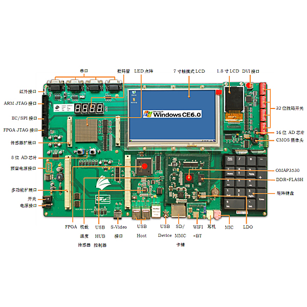


1.1CPU: OMAP3530 DCUS, 600-MHz ARM Cortex-A8 Core 412-MHz TMS320C64x+ DSP Core, integrated memory for ARM CPU (16kB I-Cache, 16kB D-Cache, 256kB L2) and on-chip storage (64kB SRAM, 112kB ROM)
1.2DDR RAM: 256MB DDR RAM MT29C2G48MAKLCJA-6IT
1.3FLASH: 256MB NAND FLASH MT29C2G48MAKLCJA-6IT
1.4 Power management: independent power management chip TPS65930
1.5LDO: With LDO
2. Baseboard hardware parameters
2.1FPGA: XC3S250E-P208 is used to control logic and expand serial ports, and assign addresses to corresponding devices
2.2 Ethernet: 1 10/100M adaptive Ethernet controller DM9000A
2.3LED: 12 GPIO controlled LED working status indicators: 6 on the core board and 6 on the bottom board
2.4 Audio: Standard AC97 audio controller small three-core interface + MIC head TPS65930
2.5 Reset: Isolate internal and external reset signals to increase reset reliability TC7SH08FU
2.6UART: 7 UARTs in total: 3 on-processor, 4 on FPGA, 1 on infrared, 2 on expansion interface, 4 on DB9 connector
2.7RTC: Independent RTC 1220 battery powered
2.87-inch LCD: 7-inch 24-bit LCD with resistive touch screen 16:9 display, resolution: 800 × 480 connected to DSS (AT070TN83)
2.91.8-inch LCD: 1.8-inch TFT LCD, resolution 128*160, connected to GPMC bus (HX8310)
2.10 Touch screen interface: SPI expands the touch screen interface, the touch screen is compatible with the 7-inch screen (TSC2046)
2.11TV-OUT: One S-VIDEO interface, mixed video signal
2.12BUFFER: With bus buffer, easy to isolate and replace
2.13DVI: One DVI interface, capable of outputting DVI-D high-definition signals with a resolution of 1280x720 and a bit rate of 30fps (TFP410)
2.14WIFI+BT: WIFI+BT+FM three-in-one module expands WG7310-00 module (WL1271) through SDIO
2.15IrDA: infrared sensor , infrared transmission (HSDL-3600#017)
2.16 Power supply: external DC power supply 12V or 5V power supply, 5A or 3A power supply
2.17 Power supply interface: 3V, 5V, 12V power supply interface reserved
2.18IIC interface: 2 IIC and 1 IIC expansion interface
2.19SDIO interface: external expansion of WIFI and Bluetooth
2.20SPI interface: 2-way SPI expansion interface
2.21 digital tube and LED dot matrix: 4 digital tubes and 1 16x16 dot matrix
2.22 Full keyboard: can expand the computer's dedicated keyboard, through the USB port expansion
2.23 matrix keyboard: 4x5 independent matrix keyboard
2.24 camera: One high-quality camera OV3640 300W pixels, can realize H.264 video real-time encoding and decoding, 30 frames per second can be used for taking pictures and video calls
2.25SD/MMC: 1 high-speed SD/MMC card interface
2.26JTAG: 1-way 20-pin ARM JTAG, 1-way 10-pin FPGA JTAG
2.27 Temperature sensor: LM75
2.28USB HOST: 4 USB HOST high-speed interfaces, support USB mouse, keyboard, Bluetooth, U disk, camera and wireless network card. Expand two-level HUB, a total of 7 av*lable USB (FE1.1)
2.29USB OTG: One Mini USB AB interface
2.30AD: 4-channel AD: 3-channel 16-bit AD7792, 1-channel 8-bit ADS1110
2.31 buttons: 6 GPIO control buttons, preset functions, user-defined functions, 4 fixed function buttons
2.32EEPROM: 16K (24C16)
2.33 DIP switch: 1 group (32 bits)
2.34 Power supply: external 12V/3A DC power supply, internal LDO voltage regulator
2.35 bus expansion interface: 192pin European socket expansion, bus, serial port, IIC, GPIO, etc., support the following optional expansion modules (optional) :
(1) Fingerprint extension module
(2) IEEE802.15.4 Zigbee expansion module
(3) FM module
2.36 SENSOR MODULE (optional) :
Expandable: 6-in-1 sensor expansion module (temperature, humidity, photoelectric sensor, pressure sensor, proximity switch, photoelectric switch)
3. Experimental requirements
3.1 Win CE Experiment
Experiment 1: Building a WINCE6.0 development environment
Experiment 2: Establishing WIN CE6.0 platform and exporting SDK
Experiment 3: Burning Windows CE
Experiment 4: Establishing a connection between the host machine and the experimental box
Experiment 5: HelloWorld experiment under VS2005
Experiment 6: Window Experiment
Experiment 7: Dialog box experiment
Experiment 8: Buzzer Experiment
Experiment 9: 1.8-inch LCD screen experiment
Experiment 10: LEDARY dot matrix experiment
Experiment 11: Eight-segment digital tube experiment
Experiment 12: LED Experiment
Experiment 13 DIP switch experiment
Experiment 14 IIC bus-temperature sensor test
Experiment 15 IIC bus-EEPROM experiment
Experiment 16 AD Experiment
Experiment 17 RS232 communication experiment
Experiment 18 RS485 communication experiment
Experiment 19 6-in-1 sensor experiment (requires 6-in-1 expansion module)
Experiment 20: Camera acquisition experiment
Experiment 21: Matrix keyboard experiment
Experiment 22 SIXKEY interruption experiment
Experiment 23: Fingerprint experiment (fingerprint module required)
Experiment 24 Zigbee experiment (need to be equipped with Zigbee module)
3.2 LINUX Experiment
Experiment 1: Install VMware Workstation software
Experiment 2: Installing the UBUNTU operating system
Experiment 3: Establishing a host cross-compilation development environment
Experiment 4: Install and configure minicom
Experiment 5: Configure HyperTerminal
Experiment 6: Configure NFS service
Experiment 7: Configure TFTP
Experiment 8 Compile x-loader
Experiment 9 Compile U-Boot
Experiment 10 Compile KERNEL
Experiment 11 Compile POMAP
Experiment 12: Deploy the file system
Experiment 13: Connecting the target board
Experiment 14: Formatting the SD card
Experiment 15: Start the system through SD card
Experiment 16: Burn the image to NAND FLASH through SD card
Experiment 17: Burn the image to NAND FLASH via TFTP
Experiment 18: Startup via NFS
Experiment 19 Simple Procedure
Experiment 20: HelloWorld Experiment
Experiment 21 GPIO Experiment SWITCH
Experiment 22 IIC experiment (read and write EEPROM)
Experiment 23 SPI Experiment (AD7792)
Experiment 24: LED dot matrix experiment
Experiment 25 Digital tube experiment
Experiment 26: LED Experiment
Experiment 27 DSP Experiment
Experiment 28: Key interruption experiment
Experiment 29: Touch screen experiment
Experiment 30: QT experiment
3.3Android Experiment
Experiment 1: Establishing the JDK application development environment under Windows
Experiment 2: Install Eclipse
Experiment 3: Install and configure ADT and Android SDK
Experiment 4: Android Simulator Operation
Experiment 5 Android Hello Application Development
Experiment 6: Install VMware Workstation virtual machine software
Experiment 8: Installing Ubuntu system in a virtual machine
Experiment 9: Establishing a host development environment
Experiment 10: Install JDK1.5
Experiment 11: Configure minicom
Experiment 12: Configure HyperTerminal
Experiment 12: Configure TFTP
Experiment 13: Compile U-boot
Experiment 14: Compile x-loader
Experiment 15 Compile the LINUX kernel
Experiment 16: Compile Android to create a file system
Experiment 17: SD mode startup
Experiment 18: Android application technical support and service
Provide hardware schematics, hardware PCB diagrams, and software design resources.
Hot products: Electrician tr*ning platform
 Wechat scan code follow us

24-hour hotline+86 18916464525

Phone18916464525
ADD:Factory 414, District A, No. 6, Chongnan Road, Songjiang Science and Technology Park, Shanghai ICP: Sitemap