Shanghai Daiyu Education Equipment Manufacturing Co., Ltd.
Language:


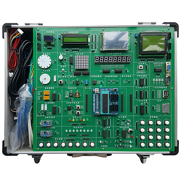


Based on the STM32 series embedded chips and the characteristics of embedded experimental teaching, the basic functional experimental circuit adopts an integrated design method, and the innovative expansion experimental circuit adopts an independent module method, which is connected to the m*nboard when needed, taking into account both demonstration and verification experiments and the needs of comprehensive design and innovative research experiments. The m*nboard has a built-in CPU programming and download interface, which is a highly flexible new embedded experimental teaching platform that integrates programming, downloading and debugging, and is suitable for students at all levels to conduct experiments and innovations in embedded principles and applications.
2. Features
1. Complete experimental guidance
A det*led experimental instruction book is specially prepared for this experimental box. I believe that with a professional experimental box and a det*led instruction book, you will quickly master the ARM embedded technology, get started quickly, and achieve twice the result with half the effort.
2. Functional modules are completely independent
Based on our years of development experience and the suggestions of users, this development board adopts the latest concept - each functional module is completely independent and does not interfere with each other, reducing programming errors for beginners. The board is equipped with rich experimental hardware resources and interfaces, and all I/O ports are open to the outside world. You can simply use the short-circuit cap to connect the default resources (convenient for beginners to use directly), or you can remove the short-circuit cap and use the DuPont line to connect any I/O port line of the microcontroller to easily build your own circuit. With a large number of C language experimental routines carefully written by our company, users can quickly master the principles of microcontrollers and their practical interface technology. At the same time, it can enhance beginners' understanding of the motherboard hardware circuit and familiarize themselves with the hardware circuit as soon as possible.
3. Support multiple CPU development experiments
The standard STM32F103C8T6 core board can be equipped with other MCU core boards according to customer needs, so as to achieve support expansion for various CPU chips.
4. Det*led Hardware Configuration
4.1 Experimental box bottom plate
4.1.1 Single color water light module: 8 high brightness green LED lights
4.1.2 Two-color water light module: 6 high-brightness LED lights, red, yellow and green
4.1.3 Dual-color LED light module: red and green dual-color LED light
4.1.4 8-bit digital tube module: 2 four-bit common anode digital tubes, 2 74HC595 driver chips
4.1.5 1-digit digital tube module: 1 8-segment digital tube, common anode, 0.56 inches
4.1.6 Red and green dual color dot matrix module: 3 74HC595 driver chips, a red and green dual color dot matrix display
4.1.7 LCD1602 LCD screen module: standard LCD1602 LCD screen interface, 1 LCD1602 LCD screen with backlight
4.1.8 LCD12864 LCD screen module: standard LCD12864 LCD screen interface, supports serial and parallel LCD screens
4.1.9 OLED display module: 0.96-inch OLED LCD screen, 128*64 display (optional)
4.1.10 TFT color screen module: The color screen adopts serial communication, supports touch screen control, and comes with a backlight switch and a 2.8-inch color screen with touch screen function and 262K colors.
4.1.11 8 independent buttons: 8 independent buttons with pull-up resistors
4.1.12 4X4 matrix keyboard: 4 rows and 4 columns matrix keyboard with pull-up resistors
4.1.13 Five-way joystick: A five-way joystick with five directions: up, down, left, right, and center
4.1.14 Buzzer module: passive buzzer
4.1.15 DS1302 clock module: DS1302 chip, module with back battery holder
4.2 Sensor Module
4.2.1 Two-way DS18B20 module: Two-way DS18B20 temperature sensor interface
4.2.2 Photosensitive sensor module: integrated LM393 comparator, reference voltage adjustable resistor, analog output interface, digital output interface, analog indicator LED light, support photosensitive diode, photoresistor and other photoelectric switch devices
4.2.3 Flame sensor module: integrated LM393 comparator, reference voltage adjustable resistor, analog output interface, digital output interface, analog indicator LED light, support flame sensor
4.2.4 Hall sensor module: integrated LM393 comparator, reference voltage adjustable resistor, analog output interface, digital output interface, analog indicator LED, supports Hall sensor
4.3 Electrical Control Module
4.3.1 DC motor interface: ULN2003 driver chip. One adjustable speed DC motor interface; One adjustable speed and adjustable direction dual function motor interface
4.3.2 2-way stepper motor interface: 2 ULN2003 driver chips. Two standard 5-wire 4-phase stepper motor interfaces
4.3.3 2-way relay: ULN2003 driver chip, two 5V relays, two 3P terminal blocks
4.4 Data transmission and storage module
4.4.1 2-way serial port: SP3232 chip, SOP16 package, +3.0v-+5V working voltage, one male serial port socket, one female serial port socket, 4 status indicator lights
4.4.2 AT24C02 storage module: AT24C02 chip, SOP8 package
4.4.3 Analog input module: 0V-5V input adjustable, 0R-10K resistance value adjustable
4.4.4 Serial-to-parallel module: 74HC164 chip, SOP14 package
4.4.5 Parallel-to-serial module: 74HC165 chip, SOP16 package
4.4.6 SD card module: standard SD card slot, SPI control, 4-bit transmission mode
4.4.7 MAX485 module: MAX485 chip, 1 set of 2P terminal block output, 1 set of pin output.
4.4.8 Infrared emission module: infrared emission diode
4.4.9 Infrared receiving module: HX838 infrared integrated receiving head
4.4.10 PCF8591 AD/DA module: PCF8591 chip, 4 analog inputs, 1 analog output, IIC communication.
4.4.11 Latch module: 74HC573 latch chip, compatible with standard CMOS
4.4.12 38 decoder: 74LS138 chip, TTL level
4.4.13 Core board expansion interface: interface socket 29P two rows, IO expansion pin 28P two rows
4.5 Power Module
4.5.1 3V3 power supply circuit: LM1117-3V3 voltage regulator chip
4.5.2 1V8 power module: LM1117-1V8 voltage regulator chip
4.5.3 Power supply lead-out: GND/5V/3V3/1V8 power supply, one group each, 6 leads per group
4.5.4 Module name: USB interface, mini USB, A-type female, D+, D-
4.5.5 Self-recovery fuse: disconnect current 300ma
4.6 Standard ARM (STM32) core module
4.6.1 Equipped with online download CPU chip STM32F103C8T6 1 piece.
4.6.2 Comes with online download circuit.
4.7 Virtual Oscilloscope
4.7.1. A true high-speed dual-channel storage virtual oscilloscope that can be switched to a single channel to increase the sampling rate.
4.7.2. With real-time XY oscilloscope: automatic synchronous display function.
4.7.3. Storage function: store/import/analyze historical waveforms.
4.7.4. The amplitude of the input analog voltage signal is adjusted by software, without the need for hardware switch.
4.7.5. A virtual oscilloscope with amplitude-frequency/phase-frequency characteristics. It can save waveform files and image files for easy insertion into teaching courseware.
4.8 Chassis
7.1 Sturdy aluminum alloy frame, thick ABS plastic corners, reference dimensions 480×360×120mm
7.2 There is a spare parts storage area of 70mm×350mm.
5. Software
5.1. Integrate a universal KEIL software environment compatible with multiple MCUs, support assembly and C language programming, compilation, linking, source level debugging and online downloading.
5.2. Online download software: STC_ISP_V479
5.3. MGCS Industrial Configuration Software
5.4、C language programming MCU application design routine
5.5、MGCS industrial configuration software and single-chip microcomputer interface routine
5. Realizable Experimental Projects
5.1 Basic Experiments
1) Marquee and running lights experiment
2) Experiments on colored water lights and traffic lights
3) Red and green color display
4) Experiments on electronic clock display, digital tube multi-digit display, 74HC595 driver, etc.
5) 1-digit digital tube display experiment
6) Can do two-color dot matrix screen display experiment, scrolling, static display characters, Chinese characters, etc.
7) LCD1602 LCD display experiment, can display characters, numbers, etc.
8) LCD12864 LCD display experiment, can display Chinese characters, letters, numbers
9)OLED display experiment, can display 4 lines of Chinese characters and pictures
10) TFT color screen image and text display. Can be used for human-computer interaction interface experiments
11) Key control, external interruption and other experiments
12) Matrix keyboard experiment, which can be used for control, teaching experiments, etc.
13) Can be used as a game joystick, realize independent button functions, etc.
14) Music playback, alarm prompts, etc.
15) Experiments on electronic watches and perpetual calendars
5.2 Sensor Experiment
1) Temperature measurement
2) Photoelectric switch experiment
3) Fire alarm, flame detection and other experiments
4) Speed measurement, electromagnetic detection and other experiments
5.3 Electrical control experiment
1) DC motor speed and direction control driving experiment
2) Stepper motor speed, direction and angle adjustment driving experiment
3) Relay control experiment
5.4 Data transmission and storage module functions
1) Serial communication, TTL to RS-232 conversion experiment
2) External storage, IIC bus learning
3) Serial to parallel experiment, can expand IO
4) Experiment of converting parallel data to serial data
5) Experiments on reading and writing SD cards and file systems.
6) With multiple sets of 485 modules, 485 communication experiments can be carried out
7) Can transmit infrared signals with different carrier frequencies
8) Infrared receiving and decoding experiment
9) AD/DA conversion
10) 8-bit data latch experiment, can be used as driver and buffer module for CPU and peripheral modules
11) IO expansion and decoding experiment
5.5 Industrial Configuration Software MCGS Programming Experiment
5.6 Application experiment of industrial configuration software MCGS in single chip microcomputer control
1) Stepper motor control experiment_bus control
2) DC motor control experiment_bus control
3) Industrial Sequential Control Experiment_Position Control
4) Data acquisition experiment_bus control
5) Data acquisition experiment_bus control
6) Digital voltmeter experiment
7) Liquid mixing control experiment
8) Traffic light control experiment
5.7 Interface programming experiment between industrial configuration software and microcontroller
Popular tr*ning products: Electrician tr*ning table
 Wechat scan code follow us

24-hour hotline+86 18916464525

Phone18916464525
ADD:Factory 414, District A, No. 6, Chongnan Road, Songjiang Science and Technology Park, Shanghai ICP: Sitemap