Shanghai Daiyu Education Equipment Manufacturing Co., Ltd.
Language:


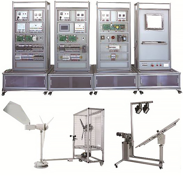


| 1. Photovolt*c power supply device | |||
| Serial number | name | Technical Parameters | quantity |
| 1 | Battery components |
Power: ≥20W Error: ±5% Output voltage: 17.2V Output current: 1.17A Open circuit voltage: 21.4V Short circuit current: 1.27A Working environment temperature: 45℃±2℃ Size: 430*430*28mm |
4 |
| 2 | Sun tracking sensor |
Output voltage: 0-5V Tracking accuracy: 1° Structure: Resistor voltage divider |
1 |
| 3 | Spotlight |
Swing arm mechanism: worm gear structure (2 reduction boxes) Voltage: 220V Frequency: 50Hz Current: 1.36A Maximum power: 500W |
2 |
| 4 | Sun Chaser |
Structure: Worm gear structure (reduction box) Drive: DC motor Number of axes: Dual axes, two dimensions |
1 |
| 2. Photovolt*c power supply system | |||
| Serial number | name | Technical Parameters | quantity |
| 1 | Photovolt*c power control unit | Including leakage protection circuit breaker, AC220V and DC24V status indicator lights, AC220V power socket, terminal block | 1 |
| 2 | Photovolt*c output display unit |
Accuracy level: 0.5 Display mode: LED Phase number: single phase Input mode: DC signal input Communication interface: RS485 (Modbus RTU protocol) |
1 |
| 3 | Photovolt*c power supply control unit |
Solar panel tracking direction: East, South, West, North Floodlight control: Light 1, Light 2Floodlight movement direction: East-West, West-East, Stop Automatic control: Start, Emergency Stop |
1 |
| 4 | touchscreen | 7",Color | 1 |
| 5 | Charge and discharge controller | Core board, interface board, signal processing board | 1 |
| 6 | PLC |
S7-200 smart CPU SR40 working power supply: AC 220V Input: 24 channels Output: 16 channels Output type: relay type |
1 |
| 7 | Adjustable resistance |
Adjustable range: 0~2000 ohms continuously adjustable Rated power: 100W Allowable deviation: ±5% Appearance: disc |
1 |
| 3. Wind power supply device | |||
| Serial number | name | Technical Parameters | quantity |
| 1 | Horizontal axis permanent magnet synchronous wind turbine |
Output power: 300W output (rectified) Voltage: > +12V Blade rotation diameter: 1m Number of blades: 3 Blade material: fiberglass Start wind speed: 1m/s Cut-in wind speed: 1.5m/s Safe wind speed: 25 m/s Yaw: program-controlled automatic yaw Yaw motor: Working voltage (DC 24V), speed (25rpm) |
1 |
| 2 | Anemometer |
Output voltage: 0~5V Number of wind bowls: 3 |
1 |
| 3 | Axial flow fan |
Flow rate: 2100m3/h Voltage: 380V (controlled by inverter) Total pressure: 215Pa Frequency: 50Hz Power: 0.37Kw Speed: 1400r/min Axial fan bracket Axial fan frame |
1 |
| 4 | Wind direction control motor |
Reduction ratio: 1:40 Voltage: AC220V Link mechanism of motion mechanism: sprocket |
1 |
| 4. Wind power supply system | |||
| Serial number | name | Technical Parameters | quantity |
| 1 | Wind power control unit | Including leakage protection circuit breaker, AC220V and DC24V status indicator lights, power socket | 1 |
| 2 | Wind output display unit |
Accuracy level: 0.5 Display mode: LED Phase number: single phase Input mode: DC signal input Communication interface: RS485 (Modbus RTU protocol) |
1 |
| 3 | Wind power control unit |
Wind field movement direction: clockwise, counterclockwise Yaw control: yaw, stop Automatic control: start, emergency stop |
1 |
| 4 | touchscreen | 7",Color | 1 |
| 5 | Charge and discharge controller | Core board, interface board, signal processing board | 1 |
| 6 | PLC |
S7-200 smart CPU SR40 working power supply: AC 220V Input: 24 channels Output: 16 channels Output type: relay type |
1 |
| 7 | Frequency Converter |
V20 voltage: 1AC220V~240V rated output power: 0.37KW |
1 |
| 8 | Adjustable resistance |
Adjustable range: 0~1000 ohms, continuously adjustable Rated power: 100W Allowable deviation: ±5% Appearance: disc |
1 |
| 5. Inverter and load system | |||
| Serial number | name | Technical Parameters | quantity |
| 1 | Inverter power control unit | Including leakage protection circuit breaker, AC220V and DC24V status indicator lights, power socket | 1 |
| 2 | Inverter output display unit |
Accuracy level: 0.5 Display mode: LED Phase: single phase Input mode: AC signal input Communication interface: RS485 (Modbus RTU protocol) |
1 |
| 3 | Inverter |
Input voltage: DC12V Input voltage range: DC9.5V-15.5V Output voltage: AC180~220V adjustable ±5% Rated output current: 1.4A Output frequency: 50Hz~60Hz adjustable ±0.5Hz Rated power: 300VA Output waveform: sine wave Waveform distortion: <5% Conversion efficiency: >85% |
1 |
| 4 | Switching Power Supply |
Model: DR-120-24 Input voltage: AC220V Output voltage: DC24V Output current: 5A |
1 |
| 5 | Frequency Converter | MM420-0.12Kw | 1 |
| 6 | Motor load |
Power: 25W Voltage: AC220V Speed: 1300rpm |
1 |
| 7 | Simulating stage lighting loads | Light-emitting module with diode lettering "KNT" | 1 |
| 8 | Lead-acid batteries |
Capacity: 12V/18Ah/20HR Weight: 1.9kg Dimensions: 345*195*20mm |
4 |
| 6. Monitoring system | |||
| Serial number | name | Technical Parameters | quantity |
| 1 | Industrial Computer | Including keyboard and mouse | 1 |
| 2 | Configuration Software | Force Control | 1 |
| 3 | Serial Gateway Server | 8-way | 1 |
| 4 | Industrial Ethernet Switches | 8-way | 1 |
| 7. New Energy Photovolt*c System Design Software | |||
| 1 | New Energy Photovolt*c System Design Software |
The m*n functions should include system design, simulation operation, financial analysis and investment estimation, economic evaluation, output design plan and feasibility study report of photovolt*c power stations, etc. It can provide authoritative meteorological data from all over the country, as well as a database of products required for various photovolt*c power stations. It must include the design of small photovolt*c power generation systems such as photovolt*c street lights and photovolt*c water pumps and the design of off-grid photovolt*c power generation systems. The design of street lights should include lighting design and lamp pole design. The design of water pumps should provide the design of two types of water pumps: DC water pumps and AC variable frequency water pumps. Provide a selection database of well-known manufacturers, and automatically display the det*led technical parameters of the product according to the selected products (photovolt*c modules, batteries, controllers, grid-connected inverters, off-grid inverters, junction boxes, etc.). After the design is completed, it can provide a det*led economic analysis, including investment and operating costs. After the design is completed, it can provide a det*led environmental benefit analysis, including greenhouse gas emission reduction and standard coal saving. The power generation and overall income of the photovolt*c power station can be calculated based on the given information, and the overall investment value of the power station can be estimated. Chinese version interface Teacher teaching design system: The system can import 3DS and STL files. It also supports re-editing this file through the system, supports AC settings, CA settings, and TA settings, connects the actions in "AC settings" and "CA settings", and can set the start and stop time of each action. It also has the functions of resetting all and deleting all. The model animation file can be loaded into the courseware through the platform supporting control for 3D animation teaching, realizing full 3D interaction in the courseware. The file can support PPT playback. Virtual spectrum analyzer, logic analyzer, oscilloscope, and three-meter simulation software: This software is in apk format and can be used on PC or mobile. The functions of this software include: resistance measurement, AC voltage measurement (measuring transformers, if the transformer burns out the multimeter, black smoke will be emitted and the multimeter can be reset), transistor polarity judgment, DC voltage measurement (the light is on when the ammeter is turned on), DC current measurement, and judgment of capacitor quality. This software allows you to drag the red and black pen tips at will. When the two pen tips are dragged to the measured object for positioning, a red circle will be displayed. If the positioning is not accurate, no red circle will be displayed. When an incorrect operation is performed (such as the wrong range is selected, the measured data is wrong, etc.), the instrument pointer will not respond, prompting an error to re-measure, etc. This multimeter can select AC voltage, DC voltage, resistance, current, resistance adjustment 0, and can enlarge the displayed data, so that the size of the measured data can be clearly viewed. Students can learn the correct use of the multimeter through this software. Virtual multimeter parameters: AC voltage range: 10, 50, 250, 1000 DC voltage range: 0.25, 1, 2.5, 10, 50, 250, 1000 Ohm range: x1, x10, 100, 1000, 1K, x10K, x100K Amperemeter range: 50μa, 0.5, 5, 50, 500 BATT: 1.2-3.6V, RL=12Ω BUZZ: R×3 Infrared emission detection function: vertical angle ±15° distance 1-30cm transistor measurement hole |
1 |
| 8. Experimental bench | |||
| Serial number | name | Technical Parameters | quantity |
| 1 | Mesh plate test bench |
The basic structure of the vertical mesh plate: the tool box + 4 wheels at the bottom, and the vertical mesh plate at the top Size: 800 (length) * 600 (width) * 2000 (height) External frame composition: aluminum alloy profile; embedded spray-coated steel plate Steel plate size: 1200 * 820mm Steel plate thickness: 2mmThe mesh plate is equipped with a push-pull drawer, which adopts a profile frame and a 2mm steel plate bottom; the bottom of the mesh frame is equipped with a pulley. |
4 |
| 2 | Microsoft operating system | Windows 7 | 1 |
| 3 | Communication Cable | cable | 1 |
| 4 | Experimental Instructions |
Wind-solar hybrid power generation system tr*ning guide |
1 |
 Wechat scan code follow us

24-hour hotline+86 18916464525

Phone18916464525
ADD:Factory 414, District A, No. 6, Chongnan Road, Songjiang Science and Technology Park, Shanghai ICP: Sitemap