Shanghai Daiyu Education Equipment Manufacturing Co., Ltd.
Language:


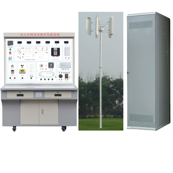


| Serial number | name | model | quantity | unit |
| 1 | Wind power grid-connected system operation console | Middle | 1 | tower |
| 2 | 2000W permanent magnet synchronous vertical axis wind turbine | Middle | 1 | tower |
| 3 | Wind blades, towers, hydraulic systems | Middle | 1 | tower |
| 4 | 3.0KW wind turbine grid-connected controller | Middle | 1 | tower |
| 5 | 2.0KW grid-connected inverter | Middle | 1 | set |
| 6 | Grid side control cabinet | Middle | 1 | set |
| 7 | Remote monitoring module | Middle | 1 | set |
| 8 | Wind resource monitoring module | Middle | 1 | set |
| 9 | Experimental attachments | Middle | 1 | set |
 Wechat scan code follow us

24-hour hotline+86 18916464525

Phone18916464525
ADD:Factory 414, District A, No. 6, Chongnan Road, Songjiang Science and Technology Park, Shanghai ICP: Sitemap