Shanghai Daiyu Education Equipment Manufacturing Co., Ltd.
Language:


| Serial number | category | name | Model Specifications | quantity | unit | Manufacturer Brand |
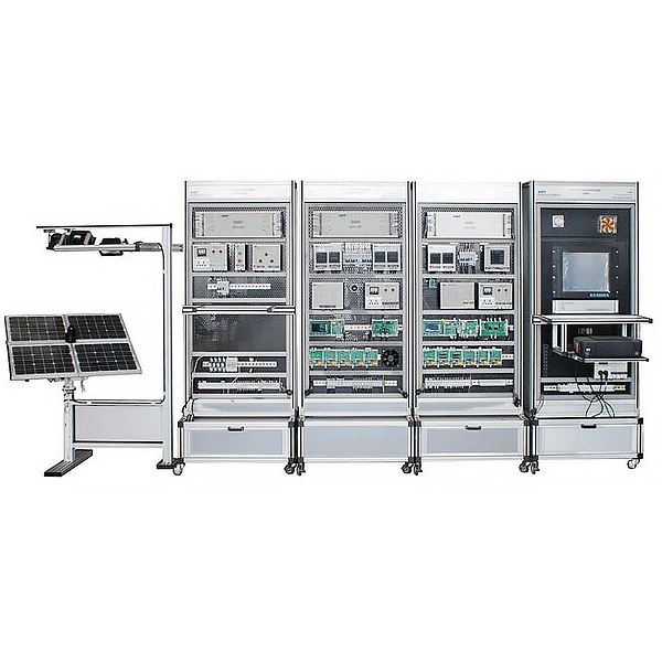
| 1 | Photovolt*c power generation tr*ning system | Light source simulation tracking device | ZRGF-PV02 | 1 | set | |
| Light source simulation control system | 1 | set | ||||
| Energy conversion control storage system | 1 | set | ||||
| Off-grid inverter load system | 1 | set | ||||
| surveillance system | 1 | set | ||||
| printer | HP Deskjet 1000 | 1 | tower | User-provided | ||
| Configuration Software | Force Control | 1 | set |
 Wechat scan code follow us

24-hour hotline+86 18916464525

Phone18916464525
ADD:Factory 414, District A, No. 6, Chongnan Road, Songjiang Science and Technology Park, Shanghai ICP: Sitemap