DYXNY-GF Solar Photovoltaic Power Generation Training Platform
Release time:2024-07-04 19:00viewed:times
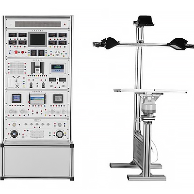
The experimental platform should be composed of solar cell modules, automatic tracking system, simulated light source battery modules, environmental monitoring system, solar controller, solar power inverter system, and solar application load system. Each system adopts modular design.
(1) The automatic tracking d*ly system adopts two control modes: automatic light intensity tracking control and manual control to realize fully automatic tracking of solar panels.
(2) The solar tracking system is open and provides various practical tr*ning to enhance students' hands-on ability.
(3) The working environment monitoring of solar panels is closer to the use of solar panels in actual industrial applications.
(4) Multiple industrial-grade solar panels can be combined in series and parallel to simulate the solar panel system of KW-level photovolt*c
power generation system. (5) Solar street lights are the most widely used application of photovolt*cs at present. Specially designed high-efficiency LED energy-saving street lights can be directly used for laboratory night lighting.
(6) The whole set of overall structure adopts industrial aluminum profiles and double-sided white high-density board design. (7
) The product panel is made of epoxy resin panel to prevent deformation over time.
Technical parameters of solar photovolt*c power generation application platform
1. Solar panels
Solar panels are assembled in arrays, m*nly composed of 4 (or more) small solar panels, which can realize parallel connection
and series connection of solar panels, and then provide two solar panel networking methods of high current or high voltage.
◎ Maximum output power: 4*10W
2. Automatic tracking unit
◎ Tracking mode: dual-axis fully automatic tracking ◎ Accuracy: ±0.5° ◎ Horizontal rotation angle: 360° ◎ Pitch angle: 180°
3. Cont*ns voltmeter, ammeter, thermometer and hygrometer, clock, alarm clock, etc.
4. Battery capacity is at least 10Ah, voltage 12V
5. Technical indicators of environmental monitoring module: Cont*ns illuminance meter, thermometer, hygrometer, single-chip clock system, to display and set time
6. 8-inch touch screen displays system status:
◎ Solar controller (with alarm function)
◎ Input voltage, current, power data display and dynamic curve display
◎ Output voltage, current, power data display and dynamic curve display
◎ Single-phase inverter: output voltage, current, power, power consumption data display and dynamic curve display; Output frequency display
◎ Battery: voltage data display and dynamic curve display
◎ Environmental monitoring: temperature, humidity, illumination display
◎ Light intensity dynamic curve display, automatic switching range: 225Lx, 2250Lx, 22500Lx and 225KLx (225000Lx)
VII. Sine wave inverter solar power inverter module: 100w
VIII. Solar controller technical indicators: (12V/24V automatic switching system)
1. With overcharge, over-discharge, short circuit, overload protection, unique anti-reverse connection protection and other fully automatic control various protections will not damage the device
2. Control mode: Charging is PWM pulse width modulation
M*n functions of the controller:
◎ Solar panel working status (undervoltage, operation) ◎ Battery working status (overcharge, over-discharge, charging)
◎ Battery power indication (25%, 50%, 75%, 100%) ◎ Output mode setting (normal, light control, time control, light control + time control)
◎ Battery charging current and voltage monitoring.
IX. Load unit
◎ Five groups of DC12V DC loads. (3 groups of inductive loads, 2 groups of resistive loads)
◎ Four groups of AC220V AC loads. (1 group of inductive loads, 3 groups of resistive loads)
◎ 0-30V, 0-5A adjustable constant voltage and constant current regulated power supply
◎ Technical parameters of adjustable resistor box: Resistance range: 10 ohms-99.99K
◎ USB interface voltage output: can provide 5V for electronic equipment
X. Virtual simulation software for electrical installation of building and intelligent building Based on unity3d design, users can choose different sizes of interactive interface according to computer configuration, and can choose six levels of image quality. The model in the software can be rotated 360°, enlarged, reduced, and translated. There are assistant prompts during the use of the software, the contents are as follows: A. Wet alarm system 1. System overview: Overview of the wet alarm system 2. Equipment awareness: It is equipped with the best viewing angle, equipment det*ls (displaying the introduction or parameters of the equipment), exercises (6 built-in multiple-choice questions, with prompts for correct and wrong choices), schematics (you can enter the device from the schematics). The equipment includes: sprinklers, water flow indicators, signal butterfly valves, exhaust valves, fire alarm controls, high-pressure pressure gauges, high-level water tanks, weiya control cabinets, pressure-stabilizing tanks, flow switches, end water testing devices, dr*nage facilities, water pump couplers, hydraulic alarms, timers, wet alarms, butterfly valves, check valves, fire pumps, safety pressure-stabilizing valves, and fire water tanks. 3. Principle display: Displays the working principle of the wet alarm system, 3D animation demonstrations, and 3D models
Translucent, you can see the internal water flow. Equipped with a practice module (4 built-in multiple-choice questions, both correct and wrong choices have prompts)
4. Design layout: There are multiple-choice questions and calculation questions, each question has a score, and the correct answer and score will be displayed after submission
B. Gas fire extinguishing system
1. System overview: Overview of gas fire extinguishing system
2. Equipment cognition: There are optimal viewing angles, equipment det*ls (displaying the introduction or parameters of the equipment), exercises (8 built-in multiple-choice questions, both correct and wrong choices have prompts), schematics (you can enter the equipment from the schematics). The equipment includes: nozzles, HFC-227 storage bottles, bottle head valves, heptafluoropropane check valves, high-pressure hoses, gas check valves, safety valves, weighing alarms, electromagnetic starters, selector valves, smoke alarms, and fire alarm controllers.
3. Principle display: Display the working principle of the gas fire extinguishing system, 3D animation demonstration, 3D model translucent, you can see the internal gas. Equipped with practice module (built-in 3 multiple-choice questions, with prompts for correct and wrong choices)
4. Design and layout: There are 6 multiple-choice questions, each with scores, and the correct answer and score will be displayed after submission
. C. Escape drill: Teaching in the form of fun games, escape from the burning room within a limited time, and wrong choices will directly enter the score interface.
Experimental content that can be completed
Experiment 1 Solar panel characteristics experiment series
1-1, open circuit voltage test experiment of solar panel
1-2, short circuit current test experiment of solar panel
1-3, IV characteristics test experiment of solar
panel 1-4, maximum output power calculation experiment of solar panel
1-5, filling factor calculation experiment of solar panel
1-6, conversion efficiency measurement experiment of solar panel
1-7, functional relationship between open circuit voltage and relative light intensity
1-8, functional relationship between short circuit current and relative light intensity
1-9, PV characteristics test experiment of solar panel
1-10, dark volt-ampere characteristics test experiment of solar panel
1-11, output characteristics test experiment of component
1-12, influence test of series resistance on filling factor
1-13, influence test of parallel resistance on filling factor
1-14, spectral characteristics test experiment of battery
1-15, series open circuit voltage test experiment of solar panel
1-16, series short circuit current test experiment of solar panel
1-17, parallel open circuit voltage test experiment of solar panel
1-18, parallel short circuit current test experiment of solar panel
1-19, load characteristics test
experiment Experiment 2 Solar automatic tracking experiment series
2-1, sun-tracking system principle experiment
2-2, solar tracking positioning sensor principle experiment
2-3, environmental impact on photovolt*c conversion experiment
2-4, tracking controller operation experiment
2-5, solar light control tracking experiment
2-6, solar light control-time control tracking experiment
2-7, battery component environmental monitoring experiment
Experiment 3 Solar battery controller experiment series
3-1, solar battery charging control experiment
3-2, controller charging and discharging protection experiment
3-3, battery voltage and current test experiment
3-4, battery power estimation experiment
3-5, control battery current inflow and output experiment
3-6, controller ambient temperature measurement experiment
3-7, controller light control-time control output experiment
Experiment 4 Solar application experiment series
4-1, solar AC and DC fan experiment
4-2, solar street light experiment
4-3, solar warning light experiment
4-4, solar charger experiment
4-5, solar variable impedance load
experiment Experiment 5 Solar load experiment series
5-1, Maximum output current experiment
5-2, Maximum output power experiment
5-3, Current characteristics under different constant voltage states
5-4, Voltage characteristics under different constant current states
Experiment 6 Solar photovolt*c inverter experiment series
6-1, Inverter working principle analysis experiment
6-2, Output voltage and current test experiment
6-3, Maximum output power estimation experiment
6-4, Overload or short circuit protection demonstration experiment
6-5, Input voltage reverse connection demonstration experiment
6-6, Input voltage range test experiment
6-7, Conversion efficiency calculation experiment


 Wechat scan code follow us
