Shanghai Daiyu Education Equipment Manufacturing Co., Ltd.
Language:


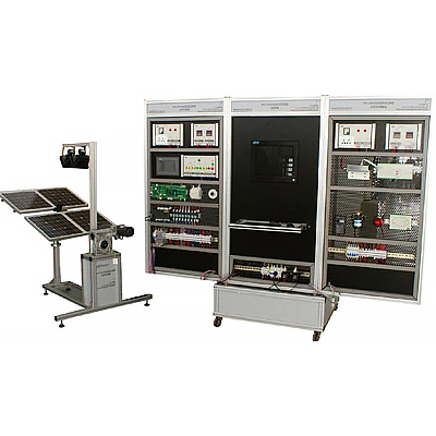


| 1. Photovolt*c power supply device | |||
| Serial number | name | Technical Parameters | quantity |
| 1 | Battery components |
Power: 20W Error: ±5% Output voltage: 17.2V Output current: 1.17A Open circuit voltage: 21.4V Short circuit current: 1.27A Working environment temperature: 45℃±2℃ Dimensions: 430×430×28mm |
4 |
| 2 | Sun tracking sensor |
Output voltage: 0-5V Tracking accuracy: 1 degree Structure: 4 bridges |
1 |
| 3 | Spotlight |
Swing arm mechanism: worm gear structure (2 reduction boxes) Voltage: 220V Frequency: 50Hz Current: 1.36A Maximum power: 300W |
2 |
| 4 | Sun Chaser |
Structure: Worm gear structure (reduction box) Drive: DC motor Number of axes: Dual axes, two dimensions |
1 |
| 2. Photovolt*c power supply system | |||
| Serial number | name | Technical Parameters | quantity |
| 1 | Power Control Unit | Including leakage protection circuit breaker, AC220V and DC24V status indicator lights, power socket | 1 |
| 2 | Photovolt*c control power unit | With leakage protection circuit breaker, AC220V and DC24V status indicator | 1 |
| 3 | touchscreen | 7",Color | 1 |
| 4 | Charge and discharge controller | Core board, interface board, signal processing board | 1 |
| 5 | DC input unit |
Ammeter: PA1951-AK1G, DC 0-5A Voltmeter: PZ195U-AK1G, DC 0-500V Interface: RS485 |
1 |
| 6 | Photovolt*c power supply control unit |
Solar panel tracking direction: East, South, West, North Floodlight control: Light 1, Light 2Floodlight movement direction: East-West, West-East, Stop Automatic control: Start, Emergency Stop |
1 |
| 8 | PLC | S7-200 CPU226 | 1 |
| 9 | Adjustable resistance | Range: 0-1000Ω, steplessly adjustable (with scale) | 1 |
| 3. Inverter and load system | |||
| Serial number | name | Technical Parameters | quantity |
| 1 | Inverter output display unit |
Ammeter: AC 0-5A Voltmeter: AC 0-500V Interface: RS485 |
1 |
| 2 | Inverter control power supply unit | With leakage protection circuit breaker, AC220V and DC24V status indicator | 1 |
| 3 | Inverter |
Input voltage: DC12V Input voltage range: DC9.5V-15.5V Output voltage: AC180~220V adjustable ±5% Rated output current: 1.4A Output frequency: 50Hz~60Hz adjustable ±0.5Hz Rated power: 300VA Output waveform: sine wave Waveform distortion: <5% Conversion efficiency: >85% |
1 |
| 4 | Switching Power Supply |
Model: DR-120-24 Input voltage: AC 220V Output voltage: DC 24V Output current: 5A |
1 |
| 5 | Frequency Converter | FR-D720S-0.4K-CHT | 1 |
| 6 | Motor load |
Power: 20W Voltage: AC220V Speed: 1300rpm |
1 |
| 7 | Simulating stage lighting loads | Light-emitting module with diode lettering "KNT" | 1 |
| 8 | Valve-regulated sealed lead-acid battery |
Capacity 12V 18Ah/20HR Weight 1.9kg Dimensions 345mm×195mm×20mm |
2 |
| 4. Monitoring system | |||
| Serial number | name | Technical Parameters | quantity |
| 1 | Industrial Computer | 5 serial ports, including keyboard and mouse | 1 |
| 2 | Configuration Software | Force Control 6.1 | 1 |
| 5. Experimental bench | |||
| Serial number | name | Technical Parameters | quantity |
| 1 | Mesh plate |
The basic structure of the vertical mesh plate: the tool box + 4 wheels at the bottom, and the vertical mesh plate at the top Size: 800 (length) × 600 (width × 2000 (height) External frame composition: aluminum alloy profile; embedded spray-coated steel plate Steel plate size: 1200mm × 820mmSteel plate thickness: 2mmSteel plate hole specifications: upper hole size 6 × 10mmThe mesh plate is equipped with a push-pull drawer, which adopts a profile frame and a 2mm steel plate bottom; the bottom of the mesh frame is equipped with a pulley. |
3 in 1 |
| 2 | Microsoft operating system software | Windows XP | 1 |
| 3 | Communication Cable | 0.3mm² two-core shielded wire | 1 |
| 4 | Experimental Instructions | Photovolt*c power generation equipment tr*ning guide | 1 |
 Wechat scan code follow us

24-hour hotline+86 18916464525

Phone18916464525
ADD:Factory 414, District A, No. 6, Chongnan Road, Songjiang Science and Technology Park, Shanghai ICP: Sitemap