Shanghai Daiyu Education Equipment Manufacturing Co., Ltd.
Language:


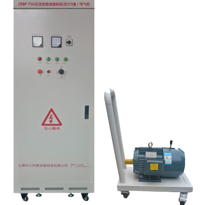


| Serial number | name | Specification | quantity |
| 7. | Leakage protection switch |
Working voltage AC400V 32A |
1 |
| 8. | Fuse holder | Melt 5A | 3 |
| 9. | Fuse holder | Melt 2A | 2 |
| 10. | AC contactor | Coil AC220V | 3 |
| 11. | AC contactor | Coil AC220V | 1 |
| 12. | Auxiliary contact | 2 NO, 2 NC | 4 |
| 13. | Motor thermal overload protector |
2.5-4A 3.2-5A |
3 |
| 14. | power switch button |
One normally open and one normally closed Automatic reset |
1 |
| 15. | Emergency stop switch |
One normally open and one normally closed Manual reset |
1 |
| 16. | Signal indicator | 220V | 4 |
| 17. | Transfer switch | 380V-440V | 1 |
| 18. | AC ammeter | 10A | 1 |
| 19. | AC voltmeter | 450V | 1 |
| 20. | Three-phase three-speed asynchronous motor (with brake) | UN380V | 1 set |
| twenty one. | Terminals | 25A | 1 batch |
| twenty two. | Wire duct | 30×30 | 1 batch |
| twenty three. | Master controller | Normally open | 1 |
 Wechat scan code follow us

24-hour hotline+86 18916464525

Phone18916464525
ADD:Factory 414, District A, No. 6, Chongnan Road, Songjiang Science and Technology Park, Shanghai ICP: Sitemap