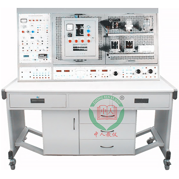
DYCBK-07 Ship electrical process experimental device
Release time:2024-07-03 22:00viewed:times
The "Ship Electrical Technology and Electrical Testing Skill Tr*ning Device" is developed based on the practical skills required by the "Outline of Competency Examination and Assessment for Seafarers" of the Maritime Safety Administration of the People's Republic of China for seafarers. It can complete the tr*ning and skill assessment of the assessment project "Ship Electrical Technology and Electrical Testing" specified by the operator-level engine management personnel. It is suitable for practical tr*ning and teaching of ship-related majors, and can also be used as skill assessment and evaluation equipment for various tr*ning institutions
and skill appr*sal stations (institutes). II. Technical Performance
1. Input voltage: three-phase four-wire (or three-phase five-wire) ~380V±10% 50HZ
2. Working environment: ambient temperature range is -5℃~+40℃ relative humidity <85% (25℃) altitude <4000m
3. Device capacity: <1.5kVA
4. Dimensions: 1680mm×805mm×1620mm
III. Device Configuration
1. AC power supply
(1) Provide a three-phase fixed 380V AC power supply, equipped with a three-phase voltage regulator (specification is 1.5kVA, 0~450V and single-phase 0~250V continuously adjustable), and an overcurrent protection device is installed at the AC power output, which can automatically protect ag*nst phase-to-phase, line-to-line overcurrent and direct short circuit. Equipped with a pointer-type AC voltmeter, it can indicate the three-phase power grid and three-phase voltage regulation output by switching on the conversion switch.
(2) There is a three-phase four-core power socket and two fixed AC 220V multi-function power sockets on the side of the control panel.
2. DC power supply
(1) Provide a 0~30V, 1A adjustable regulated power supply with soft cut-off short-circuit protection and automatic recovery function, and a voltage output indication.
(2) Two high-voltage DC power supplies: provide a 220V, 0.5A regulated power supply and a 0~250V, 3A continuously adjustable regulated power supply, and a voltage output indication.
(3) Provide one set of 90Ω×2/1.3A and one set of 900Ω×2/0.41A ceramic disc resistors.
3. Instruments
(1) One true effective value AC digital voltmeter: measuring range 0~500V, automatic range judgment and automatic switching, accuracy 0.5 level, three and a half digits display.
(2) One true effective value AC digital ammeter: measuring range 0~5A, automatic range judgment and automatic switching, accuracy 0.5 level, three and a half digits display, with over-range alarm, indication and m*n power cut-off functions.
(3) One DC digital voltmeter: measuring range 0~600V, divided into four gears of 200mV, 2V, 20V, 200V, 600V, direct key switch switching, three and a half digits display, input impedance 10MΩ, accuracy 0.5 level, with over-range alarm, indication and m*n power cut-off functions.
(4) One DC digital milliammeter: measuring range 0~2000mA, divided into three gears of 2mA, 200mA and 2000mA, switchable by direct key, three-and-a-half-digit display, precision 0.5, with over-range alarm, indication and total power cut-off functions.
(5) One power and power factor meter: composed of a microcomputer, high-speed, high-precision A/D conversion chip and full digital display circuit. Intelligent control mode of human-computer dialogue is realized through key control and digital display window. In order to improve the measuring range and test accuracy, the sampling signals of the measured voltage and current instantaneous values are converted by A/D, and the active power and reactive power are calculated by special DSP. The power measurement accuracy is 0.5, and the voltage and current ranges are 450V and 5A respectively. The active power, reactive power, power factor and load properties of the load can be measured; it can also store and record 15 groups of power and power factor test result data, and can query them group by group.
(6) Provide one three-pole double-throw transfer switch and one three-pole three-throw transfer switch.
(7) Provide one set of special resistors for energy-consuming braking and reverse braking.
4. Tr*ning components and tr*ning components
(1) Mesh operation board
Provide a st*nless steel mesh board. By matching components, students can fix, install, layout, route and debug on the mesh board by themselves, which can cultivate students' hands-on ability and operation skills.
(2) Tr*ning components
Including time relays, thermal relays, AC contactors, fuses, circuit breakers, lighted buttons, U-shaped guide r*ls, temperature relays, marine cables, etc.
(3) The tr*ning component
provides a circuit board with resistors, capacitors, diodes, triodes, thyristors, field effect transistors, single junction tubes and other components installed
to complete the test of various component parameters.
Equipped with a mirror pointer ammeter and a current transformer.
(4) An electromagnetic brake: used to detect the electromagnetic brake and adjust the gap.
(5) A small electrical control box.
(6) A set of components used for welding circuit boards and a universal circuit board
(7) A brush-type conversion switch: used for disassembly and assembly tr*ning
(8) A set of universal welding circuit boards and related components: used for welding tr*ning
(9) A set of special accessories for marine cable connections
(10) A set of marine lamps and switches: used for m*ntenance and rep*r tr*ning of marine lighting equipment.
5. Virtual simulation system for electrical safety and electric shock first *d: The software uses a combination of two-dimensional and three-dimensional virtual images to teach students electrical safety and first *d methods. The software has single-phase electric shock, two-phase electric shock, step electric shock, low-voltage electric shock first *d, high-voltage electric shock first *d, artificial respiration rescue method, hand-holding breathing rescue method, chest compression rescue method and other principle explanations and teaching. Single-phase electric shock is divided into live wire m*ntenance, socket m*ntenance electric shock, outdoor electric shock and other principle demonstrations. The teaching of low-voltage electric shock and high-voltage electric shock m*nly expl*ns and demonstrates to students how to rescue people who are in low-voltage electric shock or high-voltage electric shock. Artificial respiration rescue method, hand-holding breathing rescue method, and chest compression rescue method are displayed using 3D virtual simulation technology. After rendering and polishing, the modelIt looks exactly like the real parts, and the pictures are realistic. Through practical tr*ning, students can be educated on safe use of electricity in the tr*ning room, improve their safety awareness, learn some self-rescue methods, and take cert*n safety measures to protect themselves when encountering danger. Students can also be familiar with the causes of various electrical accidents and practical operational measures to deal with electrical accidents, thereby reducing the occurrence of electrical accidents. In order to prevent false bidding, this system demonstration is carried out at the bidding site.
6. Motor
(1) Marine three-phase squirrel cage asynchronous motor
(2) WDJ15 DC separately excited motor
(3) WDJ24 three-phase squirrel cage asynchronous motor
7. Instruments and tools
Equipped with portable digital multimeter, three-and-a-half-digit display, megohmmeter, ammeter, soldering iron, special m*ntenance tools, etc.
8. Single-chip microcomputer , PLC programmable design and control virtual simulation software (copyright certificate and demonstration video are required):
1) This software is developed based on unity3d, with built-in experimental steps, experimental instructions, circuit diagram, component list, connection line, power on, circuit diagram, scene reset, return and other buttons. After the connection and code are correct, the start/stop, forward movement, and reverse movement buttons can be used to operate the 3D machine tool model movement. When the line is connected, the 3D machine tool model can be enlarged/reduced and translated.
2) Relay control: Read the experimental instructions and enter the experiment. By reading the circuit diagram, select relays, thermal relays, switches and other components in the component list and drag and drop them into the electrical cabinet. The limiter is placed on the three-dimensional machine tool model. You can choose to cover the cover. Some component names can be renamed. Then click the connect line button to connect the terminals. After the machine tool circuit is successfully connected, choose to turn on the power and operate. If the component or line connection is wrong, an error box will pop up. The scene can be reset at any time.
3) PLC control: The experiment is the same as relay control, and the PLC control function is added. After the connection is completed, enter the program writing interface through the PLC coding button. Write two forward and reverse programs. There are 12 ladder diagram symbols in total. After writing, select Submit for program verification. After successful verification, turn on the power to operate. If there are component, line connection, and code errors, an error box will pop up. The scene can be reset at any time.
4) Single-chip microcomputer control: The experiment is the same as relay control, with the addition of single-chip microcomputer control function. After the connection is completed, enter the programming interface through the C coding button, enter the correct C language code, submit and verify successfully, turn on the power to operate, and an error box will pop up for components, line connections, and code errors, and the scene can be reset at any time.
IV. Tr*ning Projects
1. Use of multimeter
2. Detection of electronic components
3. Use of multi-purpose clamp ammeter and recognition of instrument symbols
4. Use of AC voltmeter, ammeter and power meter
5. Use of DC voltmeter and ammeter
6. Use of portable megohmmeter
7. Disassembly and assembly of AC relays, thermal relays, time relays, etc.
8. M*ntenance and parameter adjustment of temperature relays and contactors
9. Methods for measuring the gap of electromagnetic brakes
10. Welding of electronic circuit boards
11. Installation of various control circuits of motors (such as star-delta step-down starting, forward and reverse control, energy consumption braking, reverse braking, etc.)
12. M*ntenance and care of electrical control boxes
13. M*ntenance and care of marine motors
14. Adjustment and m*ntenance of brushes and commutators of DC motors
15. Use of cables
16. M*ntenance of marine lighting equipment (inspection and rep*r of marine lamps)
17. Wiring of basic marine lighting circuits
18. Selection, cutting and end connection of marine cables
19. Finding of cable insulation faults


 Wechat scan code follow us
