DYWL-01 Building Intelligent Internet of Things Training System Experimental Device
Release time:2024-07-02 19:00viewed:times
1. M*n components of the system
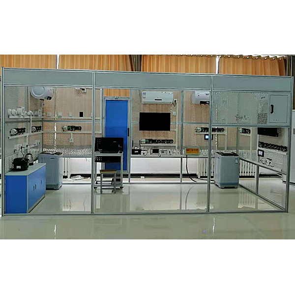
The smart home experimental system is a standard two-bedroom and one-living room smart home experimental platform. It should include seven major home control centers (entrance control center, living room control center, kitchen and dining room control center, bathroom corridor control center, master bedroom control center, second bedroom control center, balcony control center), and a set of smart home management software.
The seven major home control centers are connected to the home information interconnection processing center through Ethernet to achieve the purpose of a home comprehensive service and management integrated system composed of a home security protection system, a network service system, and a home automation system, thereby realizing a home with comprehensive security protection, a convenient communication network, and a comfortable living environment.
Description of some home control centers
(1) Dining room and kitchen control center
The dining room and kitchen control center include smart home controllers, multi-function panels, energy-saving lamps, exhaust fans, smart sockets, rice cookers, electric kettles, smoke and fire detectors, and combustible gas detectors. The multi-function panel controls the lamps and exhaust fans; the smoke and fire detectors and combustible gas detectors form a security system; the smart socket controls and collects the power and power information of the rice cooker and electric kettle, and can reasonably distribute the power load. The multifunctional panel and smart socket communicate with the smart home controller via the bus, and can also work independently.
(2) Bathroom and corridor control center
The bathroom and corridor control center includes a smart home controller, a multifunctional panel, energy-saving lamps, exhaust fans, smart sockets, washing machines, and electric water heaters. The multifunctional panel controls the lamps and exhaust fans; smoke and fire detectors and combustible gas detectors form a security system; the smart socket controls and collects power and power information of washing machines and electric water heaters, and can reasonably distribute the power load. The multifunctional panel and smart socket communicate with the smart home controller via the bus, and can also work independently.
(3) Master bedroom control center
The master bedroom control center includes a smart home controller, an expansion module, a touch screen, a multifunctional panel, a smart dimming switch, an infrared repeater, an *r conditioner and a TV, a smart socket, a smart light intensity and temperature and humidity meter, electric windows, and electric curt*ns. The touch screen communicates with the smart home controller to realize remote control, remote signaling, remote adjustment and scene mode setting; the smart dimmer switch adjusts the brightness of the incandescent lamp and can also communicate with the smart home controller through the bus to intelligently adjust the brightness of the incandescent lamp through the scene mode; the infrared detector cooperates to form a security system; the smart socket controls and collects the power supply and power information of related electrical equipment to reasonably distribute the power load; the smart light intensity and temperature and humidity meter displays and collects the temperature, humidity and illuminance of the m*n bedroom, and transmits it to the smart home controller through the bus; the electric curt*ns and electric windows cooperate with the wind and r*n detector, light intensity and temperature and humidity meter of the balcony control center to automatically open and close the curt*ns and windows, and communicate with the smart home controller through the bus.
(4) Second bedroom control center
The second bedroom is equipped with a control center, which includes a smart home controller, a touch screen, a multi-function panel, an energy-saving lamp and a smart socket. The touch screen communicates with the smart home controller through the bus to realize remote control, remote signaling, remote adjustment and scene mode setting; the multi-function panel controls the lamp; the smart socket controls and collects the power supply and power information of related electrical equipment to reasonably distribute the power load; the multi-function panel and the smart socket communicate with the smart home controller through the bus, and can also work independently.
(5) Entrance control center
The entrance control center installation includes smart home controller, multi-function panel, energy-saving lamp, doorbell, and camera. The multi-function panel controls the energy-saving lamp; the smart home controller controls the doorbell; the camera is connected to the router.
(6) Living room control center
The living room control center installation includes smart home controller, multi-function panel, energy-saving lamp, *r conditioner and TV, smart socket, infrared repeater, and router. The multi-function panel controls the opening and closing of the energy-saving lamp, and can also be turned on and off by communicating with the smart home controller; the smart socket controls and collects the power and power information of related electrical equipment, and can reasonably distribute the power load; the infrared repeater can control the remote opening and closing of the TV and *r conditioner, and the router provides a home WIFI assembly application for device networking and camera connection.
(7) Balcony control center
The balcony control center installation includes smart home controller, multi-function panel, energy-saving lamp, wind and r*n detector, and smart thermometer and hygrometer. The multi-function panel controls the energy-saving lamp, which can be controlled through the smart home controller. The wind and r*n detector detects whether there is wind and r*n, and the smart thermometer and hygrometer monitors the temperature and humidity and uploads the data through the smart home controller.
(8) Computer desk
Aluminum profile frame, steel tray and baffle.
(9) Virtual simulation software for mechanical tr*ning safety education: This software is developed based on unity3d. The software adopts the form of 3D roaming. The movement can be controlled by keyboard and the direction of the camera can be controlled by mouse. It has mechanical safety distance experiment, mechanical safety protection device experiment and mechanical safety protection design basic assessment. During the experiment, the 3D roaming screen uses arrows and footprints to prompt to move to the experimental position. The circle around the mechanical object shows the working radius. The experimental process is accompanied by a dialog box reminder of the 3D robot.
A. The content of the mechanical safety distance experiment includes the safety distance experiment to prevent the upper and lower limbs from touching the dangerous area (with 2 types of fence height and opening size). After entering, the requirements of GB23821-2009 "Safety Distance for Mechanical Safety to Prevent Upper and Lower Limbs from Touching Dangerous Areas" will pop up in front of the camera. Wrong demonstration: The experimental process is that after the human body enters the working radius of the mechanical object and is injured, the bloody screen and voice reminder are received. The machine is injured, and it returns to the original position and conducts the next experiment. The last step is the correct approach.
B. Mechanical safety protection device experiments are divided into safety interlock switches, safety light curt*ns, safety mats, safety laser scanners and other protection device experiments. Optional categories (safety input, safety control, safety output, other), manufacturers, product lists (safety interlock switches, safety light curt*ns, safety mats, safety laser scanners, safety controllers, safety relays, safety fences). The installation location has a blue flashing frame reminder. The experimental process is: select the safety fence and install it, select the safety interlock switch (or select the safety light curt*n, safety mat, safety laser scanner) and install it, select the safety controller and install it to the electrical control box, select the safety relay and install it to the electrical control box, and click the start button on the electrical control box. If you enter the dangerous area, the system will prompt an alarm sound, and the mechanical object will stop working. Select the reset button on the electrical control box to stop.
C. The basic assessment of mechanical safety protection design requires the installation of the mechanical safety system to be completed, and the safety guardr*l, safety interlock switch, safety light curt*n, safety mat, safety laser scanner, safety controller, safety relay, 24V power supply, signal light and emergency stop button to be correctly installed. The assessment is divided into ten assessment points, and some assessment points have three options, which are freely selected by students. After the final 10 assessment points are selected, submit for confirmation, and the system automatically calculates the total score and the score of each assessment point.
D. The software must be on the same platform as a whole and must not be displayed as a separate resource.
E. At the same time, the VR installation package of this software is provided to customers to facilitate users to expand into VR experiments. VR equipment and software installation and debugging are not required.
II. Experimental subjects that can be completed
1. Build the basic framework
(1) System composition and basic principle understanding
(2) System layout, installation and integrated wiring
(3) Test of each sensor unit
(4) Test of each intelligent unit
(5) System network construction, network configuration and testing
2. Intelligent module experiment (local control)
(1) HOME-STM32 smart home controller basic experiment
1.1 GPIO general IO port buzzer experiment
1.2 Ten-way isolated IO input-EXTI interrupt experiment
1.3 Eight-way IO relay output experiment
1.4 Systick system tick timing routine experiment
1.5 Ordinary timer TIM1-TIM8 experiment
1.6 IWDG watchdog system timing reset experiment
1.7 General timer TIMx experiment
1.8 SPI FLASH (SST25VF016B) read and write routine experiment
1.9 USART communication experiment
1.10 DMA serial communication experiment
1.11 System communication experiment
(2) HOME-AC DIMMER AC dimming lamp experiment
2.1 Pulse code switch principle and counting experiment
2.2 Pulse code switch to control the brightness of dimming lamp experiment
(3) HOME-INFR pyroelectric module experiment
3.1 Human infrared pyroelectric induction experiment
(4) HOME-INFRARED infrared repeater experiment
4.1 Infrared emission experiment
4.2 Infrared reception experiment
4.3 IIC memory read and write experiment
4.4 Air conditioner and TV infrared remote control experiment
(5) HOME-LIGHT multi-function panel experiment
5.1 TS04 touch button control experiment
5.2 LED lamp and incandescent lamp switch control experiment
(6) HOME-SOCKET smart socket experiment
6.1 Comprehensive experiment based on *r conditioner, washing machine, electric tea kettle, rice cooker control and power detection
(7) HOME-MOT curt*n window module experiment
7.1 Electric curt*n control experiment
7.2 Electric window control experiment
7.3 Comprehensive experiment based on electric curt*n window joint control
(8) HOME-RS485 RS485 extension experiment
8.1 RS485 communication extension experiment
(9) HOME-TEMP
9.1 Experiment on light intensity measurement based on TSL2561T (IIC) sensor
9.2 Experiment on temperature and humidity measurement based on DHT11 sensor
9.3 Comprehensive experiment on real-time display of light intensity, temperature and humidity and clock
3. System networking experiment (remote monitoring)
(1) Installation and use instructions of host computer software
(2) Networking experiment of switch quantity sensor unit
(3) Light quantity experiment (infrared, smoke detector, glass breakage, wind and r*n light sensor, etc.)
(4) Networking experiment of intelligent unit (AC dimming lamp, electric curt*n window, etc.)
(5) Network camera networking experiment
(6) Experiment on single room networking system with synchronous display and control based on MCGS touch screen and Labview
(7) Experiment on multiple room networking system with synchronous display and control based on MCGS touch screen and Labview
(8) Users can expand to various scene modes (home mode, vacation mode, sleep mode, etc.)
III. Technical parameters
1. Input power: single-phase AC220V±10% 50±2%Hz;
2. Machine capacity: ≤2kVA;
3. Appearance structure: aluminum profile frame, steel mesh plate;
4. The device provides two communication interfaces: RS-485 and Ethernet;
5. The intelligent power management system has 7 major protection functions: over-temperature, short circuit, over-current, over-voltage, under-voltage, loss of voltage, and power limitation; the power supply has a one-button locking function to prevent the leakage protector from closing when handling a fault, causing a risk of electric shock; the power supply has a fault locking function. When a fault occurs and causes tripping, it cannot be powered on manually. It can only be powered on successfully after the fault is cleared remotely; it can communicate with mobile phone APP and PC cloud platform through wireless 4G and wired Ethernet. In the absence of a network, the entire intelligent power management system in the classroom can run independently offline.
1) Smart terminal: The intelligent power management system is based on 32-bit ARM and uses a 4.3-inch color touch screen as a human-computer interaction interface. It monitors the operation of the equipment in real time, provides multiple communication modes such as Zigbee and CAN, and has a voice broadcast function. It can monitor three-phase voltage, current, power, power factor, frequency, electric energy and other parameters in real time, and the LCD touch screen monitors the value. It can monitor the fault type and number of faults of the laboratory power supply; the equipment time management includes the display of year, month, day and time; the user requests to turn on the equipment by swiping the card, and after the PC end authorizes it, the equipment can be started and used, and the PC end can schedule the start and stop of the equipment in different time periods.
2) Mobile APP: The power status interface displays the current voltage, current, reactive power, electric energy, equipment temperature, leakage current value, etc. in real time; the power data interface can intelligently search for power data in the past two years, and the setting interface can set the limited electric energy value, load value, equipment over-temperature value, over-voltage and under-voltage value, over-voltage and under-voltage recovery time value, etc. View the alarm log, operation log, fault log, etc. in the background. Control: The on and off of the smart switch can be remotely controlled in the WeChat applet.
3) PC software: Each device status information is displayed, with multiple sub-interfaces, fault analysis, power efficiency analysis, centralized management, personal center data management, user alarm location tracking and information statistics; it has functions such as administrator information modification and permission management. All devices can be turned on and off with one click, and the switch of each device can be controlled separately.
4) Backstage system: including account management, equipment management, rep*r management, user management, equipment management: ①, including monitoring management: real-time video monitoring of each classroom, one-click preview of the online and operating status of all devices, and analysis of equipment usage and running time. ②, including equipment nodes: can display the location of the device, code name, mounting status, user editing, user query, etc. Rep*r management: users can remotely report rep*rs, reflect equipment fault information, edit rep*r status, and the background can perform remote m*ntenance and follow up in time to effectively solve user equipment m*ntenance. User management: mobile phone numbers can be connected, one-to-one security encryption of accounts, real-name authentication, prevent account leakage and theft, and connect field data to the cloud platform backend database management.


 Wechat scan code follow us
