DYRGZN-6 Intelligent Connected Vehicle Simulation Experimental Device
Release time:2024-07-02 16:55viewed:times
The tr*ning platform consists of intelligent network-connected vehicles , infrastructure (sand table), mobile intelligent network-connected signal control system, mobile traffic information release system, mobile electronic police video surveillance system, Internet of Vehicles server, and digital road traffic sand table control System, smart car based on laser SLAM autonomous positioning and navigation teaching module, smart car based on deep vision learning algorithm module components
1.
Intelligent connected car
miniature smart car adopts Ackerman steering method, according to the ratio of 1:10 or 1:20 , equipped with a core processor, which can meet the requirements of long-term and high calculation examples and complex matrix operations. In addition, the CORTEX-M3 motion system processor built can accurately control the motion control cycle to 1ms. According to the teaching and tr*ning content, corresponding source code, interface functions, teaching examples, instruction manuals and other courseware are provided to facilitate teachers and students to understand, learn, apply, develop and innovate "at any time", "anywhere" and "at will". Human driving algorithm technology, remote simulation driving technology, vehicle-road collaborative development technology, etc., as well as participating in various smart car competition and exchange activities.
(1) Smart car hardware parameters
Vehicle type: 1:10 Ackerman steering racing-grade carbon fiber RC body, equipped with front and rear suspension shock absorbers and four-wheel drive differential drive system.
On-board six-core intelligent decision-making chip RK3399, with a m*n frequency of up to 1.8GHz Above;
vehicle size: 45cm long * 20cm wide * 17cm high;
steering form: front axle Ackermann steering (high-precision servo motor )
control accuracy: ±1°
drive mode: rear drive (DC reduction motor)
communication method: WIFI/ Serial communication
core sensor : ZNJ monocular camera; 9-axis IMU, high-resolution encoder; single-line high-precision lidar; 6 infrared ranging sensors; 2.4-inch full-color vehicle-road collaborative information screen; 2.4G/5G industrial-grade WIFI Module; beacon induction module, wireless charging module; lighting system: headlight*2, brake light*2, turn signal*4, including brake light display system, turn signal display system, headlight lighting system;
m*n materials: Aluminum alloy + ABS engineering plastic
operating system: supports C/C++/ROS/Ubuntu;
(2) Smart car function introduction
can realize automatic vehicle formation and car-following: smart car can independently realize multi-vehicle formation and car-following, and its Physical model ;
it can realize adaptive speed control, fixed-speed cruise, and drive according to the speed limit sign of smart cars;
it can realize that vehicles can drive and stop according to the instructions of traffic lights: smart cars can receive traffic light broadcast signals and can be controlled according to the status of traffic lights Smart car driving status (acceleration, deceleration, stop);
can realize the transplantation and verification of connected car software algorithms, and the algorithm operation cycle is controlled within 1ms;
provides vehicle control API interface and all data interfaces of nine-axis IMU, speed and angular velocity control interface, 8-channel infrared sensor data interface, camera lane recognition lane curvature algorithm interface, etc., to facilitate secondary development by university teachers and students;
it can realize the transplantation and verification of connected car software algorithms, and the algorithm operation cycle is controlled within 1ms;
it provides intelligent network Connected vehicle networking protocol and operating program demo; intelligent connected vehicles support centralized control and distributed autonomous control; provide three-dimensional traffic real-time status display system software source code.
(3) Smart vehicle sensing system
In order to ensure the safety performance of the vehicle during driving, the vehicle is equipped with an advanced intelligent assisted driving system, and the data of the intelligent assisted driving system depends on the vehicle's sensing system, which senses surrounding information and analyzes the road and road conditions. Detect and identify vehicles, pedestrians, and traffic lights. Therefore, the vehicle is equipped with a double-sided camera and a depth camera to complete passive perception of environmental information. Since the image information is rich, in order to complete the real-time processing of the image information, the vehicle system is equipped with a high-performance embedded on-board processor to complete the detection, identification, statistics and situation estimation of targets in the image.
The camera can capture various moving targets within a 120° wide-angle field of view of 20 meters. At the same time, the camera uses advanced technology to m*nt*n high image accuracy under dynamic environmental conditions. The resolution of the camera is a dual 4M pixel sensor with 2 microns, and a thermal sensor monitors the temperature to compensate for imaging deviations caused by camera heating.
In addition, the vehicle is also equipped with lidar to detect obstacles such as roads and pedestrians through laser scanning. The laser radar is driven by a DC brushless motor mechanism , and its ranging module rotates in a clockwise direction, thereby achieving a 360° all-round scan of the surrounding area, thereby obt*ning planar point cloud data in the space where it is located. The effective measurement distance of lidar is 12 meters, and the sampling frequency reaches 8000kHz. Because the lidar uses a low-power infrared laser emitter and is driven by modulated pulses, the laser completes the emission action within an extreme time, reaching the FDA CLASS I human eye safety level, and the system has very high safety.
In addition, the vehicle is also equipped with ultrasonic sensors, vehicle attitude measurement sensors and other modules to ensure that the vehicle still has high safety performance under short-distance conditions.
Each sensor module has its own advantages and limitations. The system uses sensor information fusion technology to make up for the shortcomings of a single sensor and improve the safety and reliability of the entire system in outdoor scenarios.
(4) Smart vehicle positioning system
For vehicles moving outdoors, the system selects Beidou satellite navigation and positioning as the m*n system. Through differential positioning technology, the vehicle can be accurately positioned on the road, with positioning accuracy up to centimeter level.
The vehicle-mounted positioning system is interconnected with the central control system through Internet communication technology. The central control system can track and record the status and location of the outgoing vehicle through the management platform. At the same time, it can also display the driving trajectory of the vehicle on the way out, so that the operator can Keep abreast of the vehicle's operating conditions in a timely manner so that once a deviation occurs, it can be dealt with as quickly as possible.
Specifically, the vehicle positioning system m*nly completes the following functions:
1) Vehicle monitoring. Real-time monitoring of vehicle location, driving direction, driving speed, motion status, etc. The system can be set to return the vehicle's dynamic information once every 1 second in order to grasp the vehicle's status in a timely manner.
2) Track playback. Through the analysis of historical data, the control center can check the trajectory data of the past 30 days, and at the same time improve and upgrade the optimization degree of the trajectory.
3) Remote control. The control center can remotely control the vehicle such as power off and lock at any time to ensure the safety of the vehicle under cert*n circumstances.
4) Mileage statistics and distance measurement functions. Through the statistical measurement of the vehicle's running trajectory, the online mileage statistics and driving distance measurement of the vehicle are completed.
Since the accuracy error of ordinary civilian satellite navigation and positioning systems is large, this system chooses a differential navigation and positioning system with communication base stations as differential stations. It provides accurate error information in high-precision positioning through differential stations to achieve vehicle-mounted Beidou satellite navigation. System position correction.
This module has built-in WIFI, LTE, DSRC (IEEE802.11p), and C-V2X (LTE-V) modules. It has three working modes: LTE/LTE-V/DSRC and supports 5G V2X communication. At the same time, in order to complete high-precision differential positioning information based on V2X, the system supports GPS/Beidou dual system compatibility mode, and completes the release and reception of high-precision RTK positioning enhancement information through the built-in RTK GPS module. The module title, Road Cloud Collaboration V2N, can send real-time traffic information to cloud management, and also obt*n maps, dynamic traffic and other information.
(5) The vehicle in the smart vehicle communication
system is not an independent operating entity, but several mobile terminals. Intelligent connected vehicles exchange information with each other, as well as with road infrastructure, pedestrians, etc. In order to ensure driving safety and improve traffic efficiency, the system uses DSRC technology for V2X communication. DSRC m*nly includes wireless communication and network communication functions. Wireless communication module, which requires the maximum coverage radius of the roadside unit for vehicle-to-infrastructure communication to be greater than 1km, and the single-hop communication distance between vehicles to be up to 300m. The network communication module is required to have broadcast function, multi-point broadcast, regional multicast and other functions. At the same time, the priority of messages can be set, the channel and connection interface can be freely set, and the vehicle-mounted unit also has mobile characteristics.
In order to meet the dissemination of emergency safety event messages during auxiliary driving of vehicles, the communication delay of the media access control layer of the vehicle-mounted unit is less than 40ms, the number of concurrent media services is more than 3, and the ultimate capacity of the terminal can reach 128. At the same time, at the network layer, the propagation delay of emergency security events from end to end is less than 50ms.
The SRCC module consists of a roadside unit RSU, an on-board unit OBU, a control center and some auxiliary equipment. Each fixed equipment RSU (Roadside Unit) consists of - a broadcast SAP (Service Access Point) and each mobile-specific SAP within the communication area known to the fixed equipment. When the data link layer detects a new dedicated link address, the fixed device can establish a dedicated SAP for the mobile device and establish the dedicated link. Each mobile device shall include a broadcast SAP and - when requesting uplink transmission - a private SAP. Therefore, the communication system has two working modes: point-to-point mode and point-to-multipoint mode, and adopts master-slave mode, and the control device always controls the use of physical media.
(6) Smart vehicle drive control system
The m*n tasks of the control system include task planning, behavioral decision-making and underlying vehicle control. In terms of control methods, the vehicle adopts two working modes: lateral control and longitudinal control. The lateral control mode m*nly controls the steering servo to make the vehicle drive along the desired established route while meeting cert*n stability requirements. Longitudinal control is in the driving direction, through the output PWM wave and braking system of the vehicle, so that the vehicle moves at the desired speed while m*nt*ning a cert*n distance from the obstacles ahead.
(7) Mechanical tr*ning safety education virtual simulation software: This software is developed based on unity3d. The software adopts the form of three-dimensional roaming. Movement can be controlled by the keyboard and the lens direction can be controlled by the mouse. It is equipped with mechanical safety distance experiments, mechanical safety protection device experiments, mechanical Basic assessment of safety protection design. When the experiment is in progress, the three-dimensional roaming screen uses arrows and footprints to prompt the user to move to the experimental location. The circle around the mechanical object shows the working radius. The experimental process is accompanied by a dialog box reminder of the three-dimensional robot.
A. The content of the mechanical safety distance experiment includes the safety distance experiment to prevent upper and lower limbs from touching the danger zone (divided into two fence heights and opening sizes). After selecting to enter, GB23821-2009 "Mechanical Safety to Prevent Upper and Lower Limbs from Touching the Danger Zone" pops up in front of the camera. "Safe Distance" requirements, error demonstration: The experimental process is that after the human body enters the working radius of the mechanical object and is injured, the red screen and voice prompts that the human body has received mechanical damage, and returns to the original position and conducts the next experiment. The last step is the correct approach.
B. Mechanical safety protection device experiments are divided into safety interlock switches, safety light curt*ns, safety mats, safety laser scanners and other protection device experiments. Optional categories (safety input, safety control, safety output, others), manufacturers, products List (safety interlock switch, safety light curt*n, safety mat, safety laser scanner, safety controller, safety relay, safety guardr*l). There is a blue flashing frame reminder at the installation location. Experimental process: select the safety guardr*l and install it, select the safety interlock switch (or select the safety light curt*n, safety mat, safety laser scanner) and install it, select the safety controller and install it in the electrical control box , select the safety relay and install it in the electrical control box, click the start button on the electrical control box. If you enter a dangerous area, the system will sound an alarm and the mechanical object will stop working. Select the reset button on the electrical control box to stop.
C. The basic assessment of mechanical safety protection design requires the completion of the installation of the mechanical safety system, and the correct installation of safety guardr*ls, safety interlock switches, safety light curt*ns, safety mats, safety laser scanners, safety controllers, safety relays, 24V power supplies, signal lights and Emergency stop button. The assessment is divided into ten assessment points. Some assessment points have 3 options, which are freely chosen by the students. After selecting the final 10 assessment points, submit for confirmation, and the system will automatically obt*n the total score and the score of each assessment point. .
D. The software must be on the same platform as a whole and cannot be displayed as separate resources.
E. At the same time, we provide customers with the VR installation package of this software to facilitate users to expand into VR experiments. VR equipment and software installation and debugging are not required.
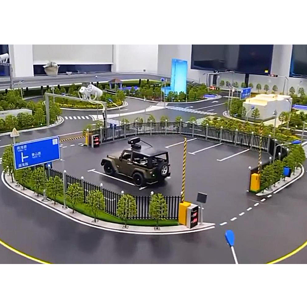
2. Infrastructure construction (sand table)
This plan builds a three-dimensional semi-physical virtual simulation sand table, and designs various experimental scenarios based on the semi-physical virtual simulation sand table and virtual simulation software, and transplants real roads, buildings , grassland, green plants, etc. in miniature. Bridges, guardr*ls, parking lots, traffic signs and other traffic environment elements have been built into a virtual simulation tr*ning platform that integrates smart cars, smart road networks, and smart management central control systems to provide immersive, three-dimensional, and virtual reality-based smart transportation. system. Among them, the shape of the road is scaled down and designed in accordance with real highway engineering construction standards, including different scene elements such as intersections, T-intersections, roundabouts, ramps, curves, gradient roads, parking areas, and landscape areas.
The technical parameters of the sand table are as follows:
the pavement layer has various driving routes, the road signs are clear and the road surface is smooth.
The functional display layer is equipped with road landscape, including traffic lights, signs and markings, street lights, lawns, gantry, cameras, speed limit signs, etc. The components of the functional display layer can be fixed on the pavement layer and subgrade layer through screws.
The sand table panel cont*ns a power control panel, and the m*n power switch, street light power supply, traffic light power supply, and ambient light power supply can all be controlled independently;
road network design: the overall road section refers to the school or city landmark road sections, etc., and the m*n part is 1:20 or 1 :10 Real design, other road sections are designed reasonably while meeting the road network design specifications and closed-loop traffic flow, and multi-angle traffic design drawings are provided.
Lane types: including two-way 4-lane, two-way 2-lane, one-way road, emergency lane, ramp, special road, etc.;
Road protection: simulated highway real-life median strip, landscape road, guardr*l, etc.;
Pavement material: beautiful and wear-resistant imitation Special materials for filtration, clear markings and smooth road surfaces;
lighting circuits: including architectural lighting, landscape lighting, street lights, decorative lighting, functional lighting, functional circuits, circuit control boxes and other lighting and circuit controls;
traffic control equipment: including Traffic guidance display boards, variable speed limit signs, flash alarm equipment and other traffic equipment;
reserved scalable electronic device interfaces, as well as secondary development interface functions and codes.
The following road elements can be set in the sand table:
Serial number Road type Number of functions
1 Multiple vehicles traveling on the road section
2 Crossroads 4 Vehicles traveling in four-way lanes
3 T-intersection 4 Vehicles traveling in three-way lanes
4 Roundabout 1 One-way counterclockwise around the island Driving
5 Parking lot 2 Parked vehicles
6 Parking fee equipment 2 Parking fee
7 Landscape with multiple perfect road elements
8 Pedestrian bridge 1 Pedestrians can safely go to the opposite side of the road section
9 Lane indicator light 4 Control the driving direction of vehicles on the road section according to the traffic volume
3. Mobile intelligence Networked signal control system
Intelligent networked signal is one of the important components of the smart urban transportation system. It is m*nly used for the control and management of urban road traffic lights, information display screens, parking space guidance screens, vehicle detection and speedometers. It can Connected to the control center platform to implement regional control and traffic optimization. The signal machine body is m*nly composed of a control box, a power distribution unit and a cabinet. The control box m*nly includes a frame, which includes a control board, a phase driver board, and a vehicle detector, which are connected together by a bus. The power distribution unit includes switches, fuses, distribution boards, power supplies, leakage protection, etc.
The signal has the following functions:
(1) Change the signal green time in real time based on the detected traffic flow data. The phase runs at least minimum green. If a vehicle passes by, an extended green time will be extended. If a vehicle continues to arrive during the extended green time, the green light time will continue to be extended until it reaches maximum green.
(2) Special functions such as phase dwell and pedestrian crossing at one time can be realized through induction.
(3) Adaptive induction control is a control method that automatically adjusts signal control parameters in real time according to traffic flow conditions to adapt to changes in traffic flow.
(4) Fixed period control performs phase signal output according to the preset control scheme. During the operation of the scheme, the cycle is long, the green signal ratio, and the phase sequence do not change with changes in road conditions.
(5) Multi-period control In different periods, the traffic status of the intersection is also different. In order to achieve better control effects, different control schemes should be set up.
(6) The signal machine can divide 24 hours a day into several periods, and each period runs the corresponding cycle and green signal ratio plan.
The signal hardware parameters are as follows:
Signal light size: length 0.4*width 0.5*height 0.5m (a bottom bracket can be installed as needed).
The indicators comply with the requirements of GB25280-2016 "Road Traffic Signal Control Machine" and have a test report from the Traffic Safety Product Quality Supervision and Testing Center of the Ministry of Public Security.
The signal control machine has complete signal control logic and output ports. It has 12 independent motor vehicle light groups, 4 independent pedestrian light groups, can connect up to 32 detectors, dual RS232 communication interfaces, and has central control, induction Control function, weak current common anode output;
meet the intelligent network connection (V2X) function, real-time broadcast of the current intersection traffic light status;
red, green and yellow intersection signal lights include arrow lights and countdown timers;
include crosswalk traffic light indication system;
can V2X adaptive control of traffic lights System;
can realize independent control, group control, designated phase release, route selection release and other functions;
degraded operation: can automatically alarm the signal machine f*lure and automatically degrade the operation.
Traffic light phase and cycle control in each direction can be set locally and in the background;
functions such as independent control, group control, remote timing, designated phase release, route selection release, etc. can be realized;
network signal data record backup and export;
4. Mobile traffic information There are many ways to release system
traffic information, and the m*n ways are as follows:
(1) Vehicle-mounted terminals
Vehicle-mounted terminals m*nly include in-car mobile digital TVs, LED information display screens and other publishing terminals. The development of vehicle-mounted computers involves GPS positioning technology, GPRS wireless communication technology, embedded software development and many other fields. In addition to the functions of ordinary vehicle terminals, vehicle-mounted terminals also have functions such as receiving wireless digital TV signals and playing digital TV programs.
(2) Electronic stop sign
The electronic traffic stop sign m*nly provides passengers on the platform with the real-time operating location of operating vehicles and the estimated arrival time of the next bus, etc., making it convenient for passengers to reasonably choose bus routes and arrange w*ting times, avoid passengers blindly w*ting for buses, and improve the level of transportation services. Electronic stop signs can be combined with traffic vehicle positioning technology to transmit the current vehicle's location and time information to the traffic information processing center through the GPRS network. The traffic information processing center then displays the processed vehicle-related information to traffic passengers through the electronic stop signs.
(3) Station and yard inquiry terminal
Station and yard inquiry terminals are generally installed at rapid transit, underground stations, light r*l stations and intelligent transportation platforms. The inquiry terminal is m*nly a touch screen. Travelers can interactively inquire about the transportation required for travel. information.
(4) Traffic Radio
Through traffic radio stations, the traffic information service department can provide traffic operation information, road conditions, r*lway, civil aviation information and other service information to radio listeners, allowing travelers to determine their driving routes as early as possible. Digital Audio Broadcasting (DAB) uses digital coding, which avoids the shortcomings of traditional FM/AM broadcasts that are susceptible to interference by terr*n and environment, and can be received during high-speed movement. In addition to sound, it can also transmit A variety of content such as text, graphics, and videos are particularly suitable for publishing data information while on the move.
(5) Traffic electronic screen
Traffic electronic screen, also known as urban traffic diversion information electronic screen, m*nly provides vehicle operating status, weather, road construction and other information to vehicles running on urban roads. Traffic electronic screens are generally divided into three types: text screen, graphic screen and comprehensive display screen. They are connected to the traffic command and dispatch center, traffic information processing center and other information service centers through access to the information exchange platform.
This solution includes traffic guidance display screens, information release screens, dynamic speed limit screens, toll display screens, etc. Users can edit independently or the host computer automatically releases relevant information, and has functions such as graphic and text editing, remote sending, and secondary development.
The technical parameters are as follows:
The system is installed on the traffic sand table and uses a 5-inch LCD screen to release traffic information.
Highway toll information release: Display vehicle toll information.
Parking lot information release: Display parking space occupancy information.
Traffic status information release: Displays road traffic status information, such as congestion, saturation, smoothness and other road traffic status.
It has a WIFI communication interface, which can realize remote configuration and emergency command information release management.
5. Mobile electronic police video surveillance system
Urban road traffic safety is an important branch of urban public transportation safety. With the large-scale popularization and application of motor vehicles, various illegal incidents related to motor vehicles have begun to spread. The road traffic safety issues derived from this have increasingly become an important constr*nt in social and economic development. Collecting, counting and analyzing road traffic accidents found that most traffic accidents are caused by illegal driving of motor vehicles, especially accidents caused by motor vehicles running red lights at intersections or road sections account for the largest proportion. By constructing a mobile electronic police video surveillance system and configuring red light running automatic recording software, this solution can simulate uninterrupted automatic detection and recording of red light running behavior of motor vehicles, as well as record and store other intersection information.
The technical parameters are as follows:
using mini camera video collection equipment, it can remotely monitor road traffic conditions;
screen splitter: push the collected video to the large display screen or host computer to realize the playback of each video screen;
for d*ly traffic management and The planning provides data support;
it can realize multi-target vehicle detection;
it provides traffic induction adjustment monitoring;
it can detect and identify simulated violations such as running red lights and f*ling to follow traffic signs.
The use of mobile electronic police video surveillance systems has the following advantages:
(1) Advancement: The electronic police front-end system uses high-definition integrated cameras to replace the analog camera + industrial computer mode, which is the most important manifestation of the system's advancement.
(2) Reliability: The electronic police front-end system widely uses embedded technology and abandons the industrial computer model. Whether it is the service life of the front-end equipment or resistance to harsh environments, the reliability has made a qualitative leap, which is in line with the development of electronic product design. direction.
(3) Economy: Using an embedded integrated high-definition camera to replace a digital camera, and an LED low-power fill light to replace a flash, the service life of the equipment is significantly longer, the product replacement cycle is significantly shortened, and the system economy is significantly improved.
(4) Security: The data collected by the electronic police front-end system is encrypted and transmitted, ensuring the security of the system data.
(5) Ease of m*ntenance: The electronic police front-end system cont*ns a small number of devices. The integrated high-definition camera accepts centralized management of the software platform and can achieve remote upgrades, m*ntenance and automatic timing.
6. Internet of Vehicles Server
Internet of Vehicles is a huge interactive network composed of vehicle location, speed, route and other information. Through GPS, RFID, sensors, camera image processing and other devices, vehicles can complete the collection of their own environment and status information; through Internet technology, all vehicles can transmit and aggregate their various information to the cloud management platform; through the management platform, these Massive vehicle information can be analyzed and processed to calculate the best routes for different vehicles, report road conditions in a timely manner and arrange signal light cycles, as well as achieve effective management and monitoring of vehicles.
Therefore, the Internet of Vehicles is inseparable from the server. The data information transmission of the Internet of Vehicles requires an Internet of Vehicles management platform to receive and process the data transmitted from the terminal. Although the vehicle is not directly related to the server, However, to achieve communication with the Internet of Vehicles management platform, and the management platform needs a server to carry it, the Internet of Vehicles and the server are inseparable.
The configuration of the server selected for this solution fully meets the technical parameter requirements, as follows:
CPU: i7 8th generation processor, 64-bit 2.4G quad-core
memory: 32GB, supports expansion to 64G memory;
WIFI: 802.11AC wireless, 2.4GHz/5GHz Dual-band WIFI
hard drive: 1TB SDD+1TB HDD;
power supply: 750W high-power power supply;
including sound card and network card;
Number of HDMI ports: 1
Number of USB interfaces: 4
with DIS display connector
Operating environment: fully compatible with ROS, Ubuntu, Linux;
supported languages: C, C++, JAVA, Python.
7. Digital road traffic sand table control system
The traffic control system uses equipment adapted to the ever-changing traffic conditions to form a system that correctly directs traffic according to traffic rules. Traffic control systems will develop from passive systems to active systems in the future. In terms of control methods, the fixed-period system control will be changed so that the period within the system can be changed at any time, increasing the flexibility of the system to adapt to instantaneous changes in traffic flow. In the control equipment, large-scale integrated electronic equipment and microcomputers will be widely used.
In this plan, the digital road traffic control system is the core function of the entire system. It can realize the motion control, path planning, task issuance, role setting, centralized dispatching, data analysis, etc. of smart vehicles; it can realize the management and control of roadside equipment, For example, setting up traffic lights at each intersection, traffic guidance display screens, electronic speed limit sign speed values, etc. can display the working and operating status of each module in real time. At the same time, it is the data br*n of vehicle-road collaboration, with multiple built-in artificial intelligence algorithms. For example; Internet of Vehicles algorithm; smart car lane changing and overtaking algorithm, path planning algorithm, vehicle formation algorithm, multi-intersection signal green wave algorithm, etc.
The control system includes the following functions:
it can support formation management of more than 10 smart vehicles, and realize multi-vehicle management and scheduling through Internet of Vehicles algorithms;
real-time collection of smart vehicle speed, acceleration, attitude, vehicle distance and other data, as well as roadside equipment data and communication data W*t for dozens of valid data.
It can control the speed, steering, path and other parameters of different smart vehicles, plan traffic operation plans, simulate traffic flow control and relief methods, and visually display vehicle operating status.
It can simulate traffic congestion, speed limit control, lane change warning, blind spot warning and other traffic warnings to remind traffic dangers and avoid traffic safety accidents.
Supports formation management of multiple smart vehicles, and realizes multi-vehicle management and scheduling through Internet of Vehicles algorithms;
real-time reception and distribution of experimental data: automatic release function is realized through wireless communication technology, and the system update frequency is not less than 10HZ;
vehicle operating status parameter display and analysis system, It can release status information of 10 vehicles or more at the same time, including speed, acceleration, and distance between vehicles in front; it can
monitor and feedback the status of facilities and equipment, and can provide prompts for equipment abnormalities or communication abnormalities
; it provides hardware communication interfaces and software communication protocol interfaces;
smart traffic guidance and information release system, which can publish information on r*n and snow weather, road congestion, traffic control, etc.;
vehicle role definition and task process control system, vehicle roles can be positioned as police cars, engineering vehicles, ambulances and other vehicle types;
real-time traffic lights at traffic intersections Monitoring, signal parameter setting, green wave belt setting system, each traffic light phase and cycle, and countdown can be displayed in real time on the system interface, the synchronization delay is not higher than 100ms;
multi-functional electronic police system, vehicle control and status real-time monitoring ;
Optimal vehicle dispatching and remote calling system;
cloud control platform data real-time collection/storage/transmission management system;
fully compatible with ROS, Ubuntu, Linux;
supported languages: C, C++, JAVA, Python.
8. Intelligent vehicles are based on laser SLAM autonomous positioning and navigation teaching module.
The hardware foundation of laser SLAM lies in lidar. Lidar is a scanning sensor that uses non-contact laser ranging technology. It detects targets by emitting laser beams and collects The reflected beam is used to form point clouds and obt*n data. These data can be generated into accurate three-dimensional images after photoelectric processing, which can accurately obt*n high-precision physical space environment information, and the ranging accuracy can reach centimeter level; it is like a p*r of "eyes", allowing the robot to have the ability to perceive the environment in real time. .
This system uses Silan A2 laser radar to complete environmental perception within a 12-meter measurement radius for the mobile car. The radar provides real-time and accurate basic map construction data for the mobile car through 8,000 laser ranging measurements per second. In addition, the system uses opto-magnetic fusion technology to completely solve the problems of traditional lidar that cause electrical connection f*lure and short lidar life due to physical contact wear.
One of the most critical technologies in mobile robots is real-time positioning and mapping, which is the so-called SLAM technology. It attempts to solve the problem of how to determine its own trajectory by observing the environment when the robot is moving in an unknown environment, and at the same time build a map of the environment.
The SLAM system is generally divided into five modules: sensor data, visual odometry, backend, mapping and loopback detection. Sensor data is m*nly used to collect various types of raw data in the actual environment. This system m*nly includes A1 lidar scanning data, video image data, etc. Visual odometry is m*nly used to estimate the relative position of moving targets at different times, including the application of algorithms such as feature matching and direct registration. The backend is m*nly used to optimize the cumulative error caused by visual odometry, including algorithm applications such as filters and graph optimization. Mapping is used for 3D map construction. Loopback detection is m*nly used to eliminate spatial accumulation errors.
After the sensor reads the data, the visual odometry estimates the relative motion (Ego-motion) at two moments. The back-end processes the cumulative error of the visual odometry estimation results. The map is built based on the motion trajectories obt*ned by the front-end and back-end. Loop detection considers images of the same scene at different times and provides spatial constr*nts to eliminate cumulative errors.
Lidar distance measurement is relatively accurate, the error model is simple, and the theoretical research is relatively mature, with more practical products.
This program supports starting from the understanding of lidar on smart cars, gradually understanding its working principle, and how to use it to carry out research on related technologies.
Understand the working principle of lidar and common types of lidar (single line, multi-line, solid state);
build a ROS operating system environment based on UBUNTU18.04;
realize the output of point cloud information of lidar and the detection of obstacles based on ROS operating system Detection;
learning based on several algorithms such as Karto, Hector, Gmapping, etc., and completing the construction of high-precision maps;
Based on the positioning and path planning under the ROS navigation function package Navigation Stack, the indoor UWB positioning system is used for global path planning;
the surrounding environment information is extracted based on the lidar point cloud for perception.
Examples of experimental projects provided are as follows:
1. Start the Silan radar node
2. Start the mobile robot chassis control node
3. Start the automatic navigation node
4. Open the rviz imaging tool
9. Smart car based on deep visual learning algorithm module
self-driving car construction This type of sensor identifies motor vehicles, non-motor vehicles, pedestrians, road signs and other elements. The usual way of collecting data is to collect image information of the vehicle ahead through a camera installed on the roof. For each sample image, a bounding box is drawn to identify the vehicle position in the image:
UBUNTU18.04 operating system environment and TENSORFLOW deep learning data system environment installation;
target detection YOLO_V5 environment configuration;
smart car vision module and video output control;
smart car based Vision realizes the recognition algorithm of lane lines;
smart cars realize the recognition algorithm of traffic signs based on vision;
smart cars can realize automatic driving and navigation under the guidance of the visual system;
car model tr*ning is completed based on YOLO_V5, and based on the tr*ned model parameters, Real-time detection of vehicles.
Examples of experimental projects provided are as follows:
1. Start the car camera
(1) Start roscore on the server
(2) Start the car camera
(3) Start the camera internal calibration in action mode
(4) Start the camera external calibration in action mode
2. Traffic light Recognition
(1) Start the recognition program
(2) Visualize the program
(3) Adjust parameters


 Wechat scan code follow us
