DYHGRG-48 Heating Network Water Conservancy Working Condition Training Platform
Release time:2024-07-01 04:00viewed:times
Technical parameters:
1. Input power: single-phase AC220V±10% 50Hz, power 120W.
2. Pump parameters: flow rate: 20L/min, head: 12m, power: 120W.
3. Flow meter range: 16-160L/h, pressure measuring tube height 1600mm.
4. Dimensions: 1800×500×2300mm, st*nless steel movable bracket with double brake wheels.
5. The virtual simulation software for electrical installation of building and intelligent building
is based on unity3d design. Users can choose different sizes of interactive interface according to computer configuration, and can choose six levels of image quality. The model in the software can be rotated 360°, enlarged, reduced, and translated. There are assistant prompts during the use of the software, the contents are as follows:
A. Wet alarm system
1. System overview: Overview of wet alarm system
2. Equipment recognition: It is equipped with the best viewing angle, equipment det*ls (displaying the introduction or parameters of the equipment), exercises (built-in 6 multiple-choice questions, with prompts for correct and wrong choices), and schematic diagrams (you can enter the equipment from the schematic diagram). The equipment includes: sprinklers, water flow indicators, signal butterfly valves, exhaust valves, fire alarm controls, high-pressure gauges, high-level water tanks, Wia control cabinets, pressure-stabilizing tanks, flow switches, terminal water testing devices, dr*nage facilities, water pump connectors, hydraulic alarms, time delays, wet alarms, butterfly valves, check valves, fire pumps, safety pressure-stabilizing valves, and fire water tanks.
3. Principle display: Display the working principle of the wet alarm system, 3D animation demonstration, and semi-transparent 3D models, so that the internal water flow can be seen. Equipped with practice module (built-in 4 multiple-choice questions, with prompts for correct and wrong choices)
4. Design layout: There are multiple-choice questions and calculation questions, each of which is scored, and the correct answer and score will be displayed after submission
B. Gas fire extinguishing system
1. System overview: Overview of gas fire extinguishing system
2. Equipment cognition: It is equipped with the best viewing angle, equipment det*ls (displaying the introduction or parameters of the equipment), practice (built-in 8 multiple-choice questions, with prompts for correct and wrong choices), schematic diagram (you can enter the equipment from the schematic diagram). The equipment includes: nozzle, HFC-227 storage bottle, bottle head valve, heptafluoropropane check valve, high-pressure hose, gas check valve, safety valve, weighing alarm, electromagnetic starter, selection valve, smoke alarm, fire alarm controller.
3. Principle display: Display the working principle of the gas fire extinguishing system, 3D animation demonstration, 3D model is semi-transparent, and the internal gas can be seen. Equipped with practice module (3 multiple-choice questions built-in, with prompts for correct and incorrect choices)
4. Design layout: There are 6 multiple-choice questions, each with a score. The correct answer and score will be displayed after submission.
C. Escape drill: Teaching is carried out in the form of fun games. Escape from the burning room within a limited time. Wrong choices will directly enter the score interface.
Experimental purpose:
Simulate the hot water pipe network, conduct various hydraulic conditions simulation change experiments, and understand the changes in the water pressure diagram of the heat network.
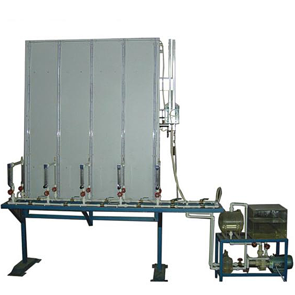
M*n configuration:
The lower half is composed of pipes, valves, flow meters, pressure regulators, boilers, and water pumps, which are used to simulate a hot water network composed of 5 users. The upper half has a high-level water tank and 12 glass tubes installed on a vertical wooden board. The top of the glass tube is connected to the atmosphere, and the lower end of the glass tube is connected to the network branch point with a hose to measure the water head (water pressure curve height) of the pressure measuring pipe of the water supply m*n and the return m*n at the connection point of the heat network user. A ruler is attached between the two glass tubes of each group of users to intuitively read the pressure at each point.


 Wechat scan code follow us
