Shanghai Daiyu Education Equipment Manufacturing Co., Ltd.
Language:


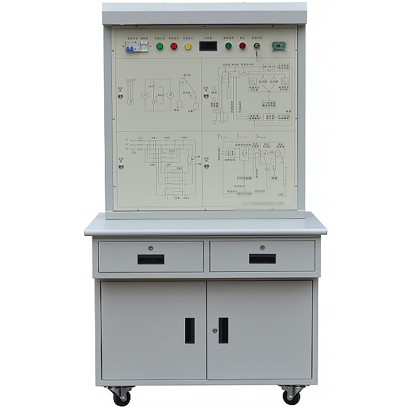


| Serial number | Product Name | quantity | unit |
| 1. | Control motherboard | 1 | piece |
| 2. | Light module | 1 | piece |
| 3. | Answer Module 1 | 1 | piece |
| 4. | Answer Module 2 | 1 | piece |
| 5. | Metal ring lighted push button | 4 | Only |
| 6. | Toggle switch | 4 | Only |
| 7. | Single phase leakage | 1 | Only |
| 8. | Fuse | 1 | Only |
| 9. | IC Reader/Writer Module | 1 | set |
| 10. | Switching Power Supply | 1 | Only |
| 11. | Digital timer | 1 | indivual |
| 12. | Lock switch | 1 | indivual |
 Wechat scan code follow us

24-hour hotline+86 18916464525

Phone18916464525
ADD:Factory 414, District A, No. 6, Chongnan Road, Songjiang Science and Technology Park, Shanghai ICP: Sitemap