DYDT-102C-4 Elevator Traction Machine Installation and Debugging Assessment Experimental Platform
Release time:2024-06-28 02:30viewed:times
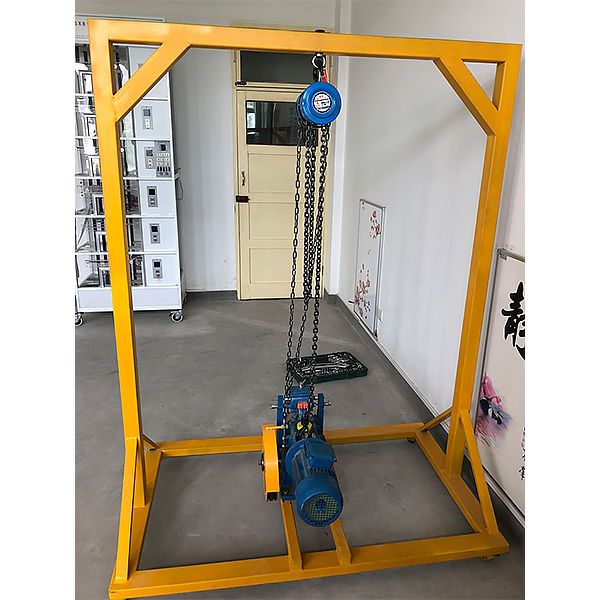
1. Equipment size: 1800×1000×2000.
2. Equipment includes:
a: Gantry - welded by square tubes, epoxy polystyrene sprayed on the surface.
b: M*n frame - 12# channel steel for the m*n frame, 12# channel steel for the machine beam, 10# channel steel for the machine beam pad, p*nted on the surface.
c: M*n machine - 100kg worm gear traction machine, fixed on the m*n frame.
d: Manual hoist - used to hoist the m*n machine.
f: Virtual simulation system for comprehensive integrated tr*ning of professional skills The model
in the software can be rotated 360°, enlarged, reduced, and translated, and has universal interactive buttons: return, home page, help. There are prompts for all virtual simulation task processes, and the software automatically ticks after completing a task. There are experimental tasks 1 and basic solids above the tool library ( the XYZ space coordinate icon automatically rotates with the rotation when the model is rotated.) A. Plane solids: The experimental steps are divided into experimental tasks (text prompt tasks) - build models (drag the model in the tool library to the three-projection surface system, and the projection will be automatically displayed. There will be prompts when the selection is wrong) - change posture (change by clicking the up, down, left, and right arrows) - select projection (enter the answering interface, and select the three-dimensional projection diagram completed at this time from the 6 items) B. Cutting solids: The experimental steps are divided into experimental tasks (text prompt tasks) - build models (drag the model in the tool library to the three-projection surface system, and the projection will be automatically displayed) - mark the projection situation (mark the three-dimensional projection diagram, and select the corresponding marking symbol in the 14 blank columns) C. Intersecting solids: The experimental steps are divided into experimental tasks (text prompt tasks) - digging holes (select any digging hole model, then you can select any surface in the XYZ space coordinates, the models will switch at the same time, and a coordinate slider will appear. According to the displacement of the slider, the model will have a corresponding degree of cross-section) - aperture change (select 1-4 apertures) - rear through hole - select projection (enter the answering interface, and select the completed three-dimensional projection diagram at this time in 8 items) 2. Assembly A. Assembly assembly: The experimental steps are divided into experimental tasks (text prompt tasks) - select the assembly model (8 models can be selected) - assemble the assembly (select the tool library model according to the selected model and drag and drop the assembly) - section the assembly (you can select any surface in the XYZ space coordinates, the models will switch at the same time, and a coordinate slider will appear. According to the displacement of the slider, the model will have a corresponding degree of cross-section) - select side projection (enter the answering interface, based on the known front and horizontal projection diagrams, select the correct side projection diagram in 3 items) B. Assembly drawing reading: The experimental steps are divided into experimental tasks (text prompt tasks) - select the assembly section view (8 types of drawings can be selected) - build the assembly model (select the tool library model according to the selected model and drag and drop the combination) - cut the assembly (you can select any surface in the XYZ space coordinates, the model will switch at the same time, and a coordinate slider will appear. According to the displacement of the slider, the model will appear with a corresponding degree of section) - select the left view (enter the answer interface, according to the known m*n view and top view, select the correct left view from the 3 items) 3. Assembly A. Mechanical transmission mechanism : 8 mechanisms (worm gear, gear rack, spiral transmission, plane external meshing gear, plane internal meshing gear, space spur bevel gear, belt drive , ch*n drive) are optional. After selecting, the model will appear in the toolbar. Drag the model freely to combine. After the combination is completed, the model can be operated. Each mechanism comes with an introduction, video demonstration, and drawing method. There are 6 questions in the answer interface, and each question has 4 options. B. Gear oil pump: Select the tool library model according to the prompts and build the model step by step. You can choose to learn the introduction, drawing method, and animation principle (the internal movement principle of the model can be visualized). There are 2 questions in the answering interface, and 4 options for each question. C. Mechanical mechanism construction: 2 mechanisms (2-degree-of-freedom robotic arm, 3-degree-of-freedom robotic arm). Select the tool library model according to the prompts and build the model step by step. After the combination is completed, the model can be operated. Each mechanism has an introduction and video demonstration. There are 2 questions in the answering interface (both models must be built before entering), and 4 options for each question. 3. The equipment can achieve the following teaching objectives: a. Understand the structure and installation principle of the traction machine. b. The traction machine can be hoisted by the gantry.


 Wechat scan code follow us
