Shanghai Daiyu Education Equipment Manufacturing Co., Ltd.
Language:

PRODUCT

PRODUCT CENTER

DYLY-PSB Building Water Supply and Drainage Electrical and Automation Training System Training Platform

Release time:2024-06-21 02:30viewed:times
  • DYLY-PSB Building Water Supply and Drainage Electrical and Automation Training System Training Platform
1. Overview  The overall
water supply and dr*nage object model is designed with aluminum profile frame and mesh plate. The m*n water supply and dr*nage pipeline equipment is installed on the steel frame base and has the characteristics of openness. It consists of six parts: domestic water supply system, fire water supply system, hot water supply system, dr*nage system, sewage treatment system and control system. 
2. Functional characteristics: 
1. St*nless steel water tray, cold and hot dual-use faucet, simulates a two-story building , mesh room, and 4 household water terminals 
2. Water pool: Made of st*nless steel, one input and four outputs, providing a constant water source to each system, equipped with a float switch and exhaust hole to ensure the water level of the pool. 
3. Three-phase water pump: two units, providing power for the constant pressure water supply system 
4. Single-phase water pump: three units, providing power for the heating system, *r pressure water supply system and water pump and water tank combined water supply system 
5. Pressure transmitter: detect the current pressure value in the water pipe of the constant pressure water supply system, and can detect 0-400KPa pressure 
6. Diaphragm pressure gauge: detect the current pressure value in the water pipe of the constant pressure water supply system, and can detect 0-400KPa pressure 
7. High-level water tank: a water storage device for the water pump and water tank combined water supply system, which provides water source to the user terminal during the water pump and water tank combined water supply tr*ning, and has high and low water level switches to realize automatic start and stop of the water pump 
8. Air pressure water tank: *r pressure supply Water storage device of water system, pressure water supply system provides pressure water source to user terminal during tr*ning 
9. High and low pressure switch: detect the current pressure of the pipeline of pressure water supply system, and provide signal for starting and stopping the water pump 
10. Pressure gauge: detect the current pressure of the pipeline of pressure water supply system, and can detect 0-1MPa pressure 
11. Water heater: provide heat source for heating/heating system, with built-in temperature detection and control circuit 
12. Heat sink: made of steel pipe and copper sheet, transfers heat in hot water to indoor *r 
III. Equipment composition and characteristics 
1. Domestic water supply system: m*nly composed of water supply tank, water supply pump, water supply pipeline, pressure transmitter, pulse water meter, faucet and shower head. The pipeline is designed with st*nless steel composite pipe, which can be cut, installed and tested for water flow. The control system can realize the variable frequency constant pressure water supply function of domestic water supply system, and realize single pump variable frequency control or double pump switching control and other functions; the pulse water meter can complete the measurement of water consumption. 
2. Fire water supply system: m*nly composed of water supply tank, sprinkler pump, pressure regulating tank, wet alarm valve, pressure switch, water flow indicator, fire water supply pipeline, closed sprinkler head, etc. The pipeline is designed with galvanized pipe, which can be cut, threaded, installed and tested for water flow. The sprinkler fire extinguishing function can be realized through the control system. 
3. Hot water supply system: m*nly composed of electric heating boiler, hot water supply pipeline, faucet and shower head. The pipeline is designed with PPR pipe, which can be cut, welded, installed and tested for water flow. The boiler can be temperature-controlled. 
4. Dr*nage system: m*nly composed of sewage tank, liquid level sensor , dr*nage pump, dr*nage pipeline and water treatment unit. The dr*nage pipeline is m*nly designed with UPVC pipe, which can be cut, bonded, installed and tested for water flow. Combined with the control system, the water level detection of the sewage tank and the start and stop control of the dr*nage pump can be realized. 
5. Virtual simulation software for electrical installation of building and intelligent building Designed based on unity3d, users can choose different sizes of interactive interface according to computer configuration, and can choose six levels of image quality. The model in the software can be rotated 360°, enlarged, reduced, and translated. There are assistant prompts during the use of the software, as follows: A. Wet alarm system 1. System overview: Overview of wet alarm system 2. Equipment recognition: It has the best viewing angle, equipment det*ls (displaying the introduction or parameters of the equipment), exercises (built-in 6 multiple-choice questions, with prompts for correct and wrong choices), schematic diagram (you can enter the equipment from the schematic diagram). The equipment includes: sprinkler, water flow indicator, signal butterfly valve, exhaust valve, fire alarm control, high pressure gauge, high-level water tank, Weiya control cabinet, pressure regulating tank, flow switch, end water test device, dr*nage facilities, water pump connector, hydraulic alarm, delay, wet alarm, butterfly valve, check valve, fire pump, safety pressure regulating valve, fire water tank. 3. Principle display: Display the working principle of the wet alarm system, 3D animation demonstration, 3D model is semi-transparent, and the internal water flow can be seen. Equipped with exercise module (4 multiple-choice questions are built-in, and there are prompts for correct and wrong choices) 4. Design layout: There are multiple-choice questions and calculation questions, each of which is scored, and the correct answer and score are displayed after submission B. Gas fire extinguishing system 1. System overview: Overview of gas fire extinguishing system 2. Equipment recognition: There are optimal viewing angles, equipment det*ls (displaying the introduction or parameters of the equipment), exercises (8 built-in multiple-choice questions, and there are prompts for correct and wrong choices), and schematic diagrams (you can enter the equipment from the schematic diagram). The equipment includes: nozzles, HFC-227 storage bottles, bottle head valves, heptafluoropropane check valves, high-pressure hoses, gas check valves, safety valves, weighing alarms, electromagnetic starters, selection valves, smoke alarms, and fire alarm controllers. 3. Principle display: Display the working principle of the gas fire extinguishing system, 3D animation demonstrations, and 3D models are semi-transparent, and the internal gas can be seen. Equipped with practice module (built-in 3 multiple-choice questions, with prompts for correct and wrong choices) 4. Design layout: There are 6 multiple-choice questions, each with a score, and the correct answer and score will be displayed after submission . C. Escape drill: Teaching in the form of fun games, escaping from the burning room within a limited time, and wrong choices will directly enter the score interface. 5. Automatic water supply and dr*nage control system: 

Serial number  Control Name  Specification  quantity 
1.      Tr*ning table    1 piece 
2.      Electrical control tr*ning screen    1 set 
3.      Inverter module  MM420, three-phase 380V input, 0.75kW, with BOP panel  1 block 
4.      plc module  CPU224XP14DI/10DO, 2AI/1AO 1 block 
5.      Analog Modules  EM235 4AI/1AO 1 block 
6.      Touch screen module  7-inch MCGS7026 1 block 
7.      Pulse water meter  0.01 cubic meter/pulse  1 block 
8.      Pressure Transmitters  Range 0-200KPa 1 block 
9.      Low voltage electrical  Small relays, AC contactors, thermal overload relays  1 set 
10.  Configuration Software  Supporting configuration software and water supply and dr*nage system configuration monitoring program, through the computer to monitor and control the water supply and dr*nage system online,  1 set 
IV. M*n technical performance
  1. Working power supply: three-phase four-wire AC380V±10% 50Hz; 
2. Dimensions of water supply and dr*nage model: 120cm×120cm×220cm (length×width×height); 
Dimensions of water supply and dr*nage simulation room: 300cm×150cm×190cm (length×width×height); 
Dimensions of water supply and dr*nage m*n control cabinet: 80 cm×60 cm×170cm (length×width×height)
3. Material of water supply and dr*nage model: st*nless steel; 
4. Power consumption of the whole machine: <4.5KVA; 
5. Casters with brakes are installed at the bottom of the device to facilitate the movement and fixation of the device; 
6. Safety protection measures: It has grounding protection, leakage overload protection, and misoperation protection functions; the safety meets the relevant national standards, and all materials meet environmental protection standards. 
V. Practical project 
water supply and dr*nage and automation experiment content 

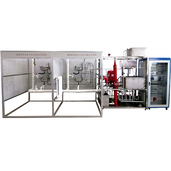
1. Understanding of water supply and dr*nage system 
2. Common components and system composition of graded dr*nage system 
3. Installation of accessories and components 
4. Pipeline pressure test and water flow test 
5. Principle and workflow of water supply system 
6. Operation practice of variable frequency constant pressure water supply system 
7. Principle and workflow of *r pressure water supply system 
8. Operation practice of *r pressure water supply system 
9. Principle and workflow of water pump and water tank combined water supply system 
10. Operation practice of water pump and water tank combined water supply system 
11. Working principle and workflow of heating system 
12. Heating system operation practice 
13. Electrical design, installation and wiring 
14. Frequency conversion control program design and debugging 
15. Meter reading and billing program design 
16. Sprinkler fire extinguishing control program design 
17. Water supply and dr*nage monitoring program design 
18. Configuration monitoring system design 
19. Understand the material composition of community sewage 
20. Understand the sewage treatment device and master its operation method 
21. Master its treatment process 
22. Learn to use related instruments 

DAIYUWechat scan code follow us

  • 24-hour hotline+86 18916464525

  • Phone18916464525

 ADD:Factory 414, District A, No. 6, Chongnan Road, Songjiang Science and Technology Park, Shanghai ICP: Sitemap