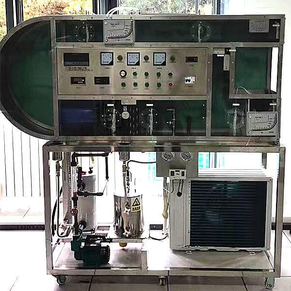
DYLR-XH Circulation Air Conditioning Process Experimental Platform
Release time:2024-06-19 04:00viewed:times
Experimental purpose:
It can be used to conduct experiments on *r conditioning processes such as heating, humidification, cooling and drying. There are two types of *r quality treatment: surface cooler and water spraying.
M*n configuration:
plastic, organic glass *r duct; orifice flowmeter, differential pressure sensor , rectifier, heater, st*nless steel humidifier, sprinkler, surface cooler, low noise axial flow fan, temperature test system, humidity test system, compressor, condenser, titanium package evaporator, liquid storage tank, copper hand valve, st*nless steel humidification water tank, anti-corrosion water pump, rotor flowmeter, 16-way universal signal input inspection instrument to display temperature, humidity, wind differential pressure, electric control box, st*nless steel bracket.
Technical parameters:
1. Input power: three-phase AC380V±10% 50Hz, power 5.0KW.
2. Temperature: 10~25℃, pressure: 0~15MPa, humidity: 10~40RH%, flow rate: 0~1000L/h.
3. Compressor: cooling capacity 950Kcal/n, refrigerant R12, heating capacity 3.0KW.
4. Evaporator heat exchange area: 15m2, heat exchanger heat exchange area: 15m2.
5. Evaporator water tank: size 650×400×450mm, 304 st*nless steel.
6. Low noise axial flow fan: flow rate 2000m3/h, power 370W.
7. Water pump parameters: flow rate: 30L/min, head: 20m, power: 370W. Flow meter range 40-400L/h.
8. The temperature is measured by a high-precision temperature sensor, and the universal signal input inspection instrument is combined with a high-precision digital display to display all experimental measurement parameters such as temperature, resistance, flow rate, power, etc. The manual damper adjusts the *r volume.
9. Overall dimensions: 2800×600×1900mm, the appearance is a st*nless steel movable bracket with double brake wheels.
10. Single-chip microcomputer , PLC programmable design and control virtual simulation software:
This software is developed based on Unity3D, with built-in experimental steps, experimental instructions, circuit diagrams, component lists, connection lines, power on, circuit diagrams, scene reset, return and other buttons. After the connection and code are correct, the 3D machine model can be operated by the start/stop, forward motion, and reverse motion buttons . When the line is connected, the 3D machine model can be enlarged/reduced and translated.
1. Relay control: Read the experimental instructions and enter the experiment. By reading the circuit diagram, select relays, thermal relays, switches and other components in the component list and drag and drop them into the electrical cabinet. The limiter is placed on the 3D machine model. You can choose to cover the cover. Some component names can be renamed. Then click the connection line button to connect the terminals to the terminals. After the machine circuit is successfully connected, choose to turn on the power and operate. If the component or line connection is wrong, an error box will pop up, and the scene can be reset at any time.
2. PLC control: The experiment is the same as relay control, with the addition of PLC control function. After the connection is completed, enter the program writing interface through the PLC coding button, write two programs, forward and reverse, with a total of 12 ladder diagram symbols. After writing, select Submit to verify the program. After successful verification, turn on the power to operate. Error boxes will pop up for components, line connections, and code errors, and the scene can be reset at any time.
3. MCU control: The experiment is the same as relay control, with the addition of MCU control function. After the connection is completed, enter the programming interface through the C coding button, enter the correct C language code, and submit the verification successfully. Turn on the power to operate. Error boxes will pop up for components, line connections, and code errors, and the scene can be reset at any time.


 Wechat scan code follow us
