DYLR-518 Air Conditioning Refrigeration and Heating Principle Experimental Platform
Release time:2024-06-18 23:30viewed:times
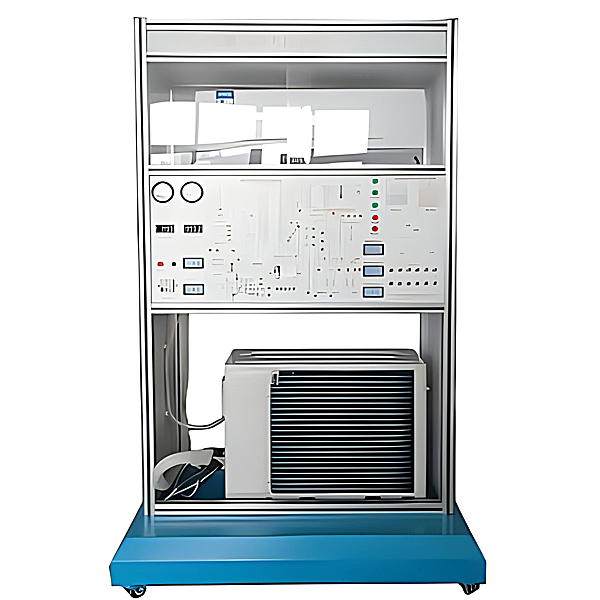
1. Overview ZRLR-518 *r conditioning tr*ning and assessment device is developed and designed for refrigeration
and *r conditioning majors in colleges, universities and secondary vocational schools . It is suitable for teaching and tr*ning requirements such as refrigeration principles and applications, refrigeration and *r conditioning technology, and refrigeration equipment m*ntenance and operation. The device integrates refrigeration system, electrical control system, and fault simulation system. It has a reasonable structure, beautiful appearance, and easy operation. It is a must-have equipment for refrigeration majors. 2. Experimental items * Basic operation of special tools for refrigeration system * Welding of refrigeration system pipelines * Leakage detection of refrigeration system * Vacuuming and refrigerant filling of refrigeration system * Fault analysis and troubleshooting of variable frequency *r conditioner * Detection of electrical components of variable frequency *r conditioner 3. Technical performance Working power supply: AC220V±5%, 50Hz Maximum remote control distance: 8 meters, angle: 90 degrees Noise: 23-37dB for indoor unit and 55-65dB for outdoor unit Cooling and heating type: Cooling and heating type Air conditioning capacity: large 1.0P frequency conversion/fixed frequency: frequency conversion Energy efficiency ratio: 4.06 Energy efficiency level: Level 3 energy efficiency Refrigeration power: 780 (200-1300) W Refrigeration capacity: 2600 (500-3100) W Circulation *r volume: 580m3/h Experimental bench specifications: 1600×700×1180mm 4. Single chip microcomputer , PLC programmable design and control virtual simulation software: This software is developed based on Unity3D, with built-in experimental steps, experimental instructions, circuit diagrams, component lists, connection lines, power on, circuit diagrams, scene reset, return and other buttons. After the connection and code are correct, the 3D machine model can be operated through the start/stop, forward motion, and reverse motion buttons . When the line is connected, the 3D machine model can be enlarged/reduced and translated. 1. Relay control: Read the experimental instructions and enter the experiment. By reading the circuit diagram, select relays, thermal relays, switches and other components in the component list and drag and drop them into the electrical cabinet. The limiter is placed on the 3D machine model. You can choose to cover the cover. Some component names can be renamed. Then click the connection line button to connect the terminals to the terminals. After the machine circuit is successfully connected, choose to turn on the power and operate. If the component or line connection is wrong, an error box will pop up, and the scene can be reset at any time. 2. PLC control: The experiment is the same as relay control, with the addition of PLC control function. After the connection is completed, enter the program writing interface through the PLC coding button, write two programs, forward and reverse, with a total of 12 ladder diagram symbols. After writing, select Submit to verify the program. After successful verification, turn on the power to operate. Error boxes will pop up for components, line connections, and code errors, and the scene can be reset at any time. 3. MCU control: The experiment is the same as relay control, with the addition of MCU control function. After the connection is completed, enter the programming interface through the C coding button, enter the correct C language code, and submit the verification successfully. Turn on the power to operate. Error boxes will pop up for components, line connections, and code errors, and the scene can be reset at any time.


 Wechat scan code follow us
