DYLR-YX compressor performance training device
Release time:2024-06-18 07:00viewed:times
1. Overview
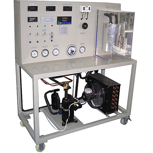
The "Compressor Performance Test Bench (Electric Calorimeter Method)" adopts a steam compression refrigeration cycle system, equipped with refrigeration compressors, st*nless steel condensers, evaporators and other real refrigeration system components, and is equipped with a color control screen, refrigerant flow control controller, electronic expansion valve, turbine flow meter, pressure transmitter, voltage, current, power, combined active power, reactive power of each phase, combined reactive power, apparent power of each phase, combined apparent power, collector. Not only can it be used to set up tr*ning on the determination of refrigeration compressor performance parameters, but also to demonstrate the basic principles of refrigeration cycle. It is suitable for teaching and tr*ning of related courses in refrigeration majors in vocational colleges.
2. Features
1. This tr*ning device is in accordance with: the test parameters comply with the provisions of GB/T 5773-2016 Performance Test Method for Volumetric Refrigerant Compressors. The compressor performance tr*ning method is established. Through this experiment, you will be familiar with and understand the test conditions and test methods of refrigeration compressors, enhance your understanding of refrigeration compressors, and use the heat emitted to offset the cooling capacity of the compressor to achieve balance.
2. In the experiment, the electric calorimeter group puts the evaporator in a closed cont*ner, and uses the electric calorimeter method to determine the cooling capacity of the compressor, the cooling capacity and power under standard working conditions, and calculate the refrigeration coefficient. It can also perform heat balance calculations and realize two working conditions with and without heat regeneration.
3. The electric calorimeter is equipped with a glass sight glass to observe the liquid level of the second refrigerant.
4. A 1-horsepower refrigeration unit is used, and the condensers are all shell and tube water heat exchangers. The system has a compact structure, a reasonable layout, and a beautiful shape.
5. It is equipped with voltage-type leakage protection, current-type leakage protection, overcurrent protection, overload protection, and grounding protection, which can effectively protect people and equipment
. 6. Touch screen and refrigeration system control: Students can give simulated temperatures on the software or touch screen, analyze the working data of the *r conditioner under various temperature conditions, and accumulate data for future actual m*ntenance and design. Real-time, historical, and export. Convenient
III. Technical performance
1. Input power: single-phase three-wire ~ 220V ± 10% 50Hz
2. Working environment: temperature -10℃ ~ +40℃ relative humidity <85% (25℃) altitude <4000m
3. Device capacity: <4kVA
4. Refrigerant: R22
5. Cooling capacity: 1.3kW
6. Weight: 100kg
7. Dimensions: 120cm×60cm×142cm
8. DC power supply: DC24V, 2A
9. Turbine flowmeter: 4-20MA, flow 3T
10. Refrigerant controller: DC24V, 2A, communication 232
11. Second refrigerant saturation pressure gauge: 1MP
12: Temperature uses PT100 sensor : Class A, measurement range -50~+150℃ accuracy 0.1℃.
13. With multi-channel standard signal acquisition, using RS485 communication, the communication protocol is MODBUS.
14.1P Supercooler
IV. Basic configuration and functions
1. Experimental table : It adopts a double-layer matte dense spray structure with a novel shape. The refrigeration system is arranged on the top layer, which can intuitively display the structure of the refrigeration system; the front is equipped with a power control and measuring instrument function board. The bottom is equipped with four universal wheels with brakes for easy movement and fixation.
2. Intelligent multi-functional control screen:
1) Controlled by a color touch screen, it can control the refrigerant flow online and arbitrarily, and can make the compressor work under various pressures and temperature environments, thereby providing various status data for the experiment.
2) At the same time, the online compressor displays current, voltage, active power of each phase, active power of all phases, reactive power of each phase, reactive power of all phases, apparent power of each phase, apparent power of all phases, power factor of each phase, power factor of all phases, frequency, active power of each phase, total active power, reactive power of each phase, total reactive power.
3) Through the touch screen, there are 11 temperatures and curves, including compressor suction port temperature, compressor exhaust port temperature, condenser outlet temperature, evaporator inlet temperature, condenser water inlet temperature, condenser water outlet temperature, evaporator water inlet temperature and evaporator water outlet temperature.
14 temperatures use PT100 sensor: Class A, measurement range
3. Refrigeration system: electric heater, 1P fully enclosed compressor, condenser, sight glass, filter dryer, expansion valve, liquid storage device and evaporator
(1) Heater 1 (power 2000W)
output power can be adjusted by, used to heat the evaporator circulating water, and measure the heating power respectively. The intelligent control mode of human-computer dialogue is realized through a large touch screen and a digital display window. The active power, reactive power, power factor, voltage, current, frequency and properties of the load can be measured; and the test data of the power factor can be stored.
5. Measuring instruments:
(1) 2 vacuum pressure gauges (accuracy level 2.5)
with a range of -0.1~1.5MPa and -0.1~3.5MPa, respectively, measure the low-pressure side pressure and high-pressure side pressure of the refrigeration system in real time, and display them on the control screen at the same time
. 6. Control instrument
1 high and low pressure controller: real-time monitoring of the low-pressure side pressure and high-pressure side pressure of the refrigeration system. When the high pressure is higher than the set value or the low pressure is lower than the set value, the controller sends a control signal to cut off the power supply of the compressor.
7. Single-chip microcomputer , PLC programmable design and control virtual simulation software: This software is developed based on unity3d, with built-in experimental steps, experimental instructions, circuit diagrams, component lists, connection lines, power on, circuit diagrams, scene reset, return and other buttons. After the connection and code are correct, the three-dimensional machine tool model
can be operated through the start/stop, forward motion, and reverse motion buttons.Movement, when the line is connected, the 3D machine model can be enlarged/reduced and translated.
1. Relay control: Read the experimental instructions and enter the experiment. By reading the circuit diagram, select relays, thermal relays, switches and other components in the component list and drag and drop them into the electrical cabinet. The limiter is placed on the 3D machine model. You can choose to cover the cover. Some component names can be renamed. Then click the connect line button to connect the terminals to the terminals. After the machine circuit is successfully connected, choose to turn on the power and operate. If the component or line connection is wrong, an error box will pop up. The scene can be reset at any time.
2. PLC control: The experiment is the same as relay control, and the PLC control function is added. After the connection is completed, enter the program writing interface through the PLC coding button. Write two forward and reverse programs. There are 12 ladder diagram symbols in total. After writing, select Submit to verify the program. After successful verification, turn on the power to operate. If there are component, line connection, and code errors, an error box will pop up. The scene can be reset at any time.
3. Single-chip microcomputer control: The experiment is the same as the relay control, with the single-chip microcomputer control function added. After the connection is completed, enter the programming interface through the C coding button, enter the correct C language code, submit the verification successfully, and turn on the power to operate. Errors in components, line connections, and codes will pop up a prompt error box, and the scene can be reset at any time.
V. Practical tr*ning projects
1. Refrigeration capacity and heating capacity experiments under standard working conditions
2. Simulate the impact of changes in various refrigeration system parameters on refrigeration performance and heating energy efficiency ratio
3. Calculation of m*n performance parameters of the system
4. Fixed frequency compressor performance test
5. Perform refrigeration cycle process and heat pump demonstration, and observe the evaporation and condensation process of the refrigerant and the working phenomenon of the compressor.
6. Study the performance of the heat pump at different cooling temperatures. 7.
Changes in the electrical power and rated power of the equipment
8. Demonstrate the compression refrigeration cycle under different conditions and the energy balance in the system.
9. Study the refrigeration efficiency and refrigeration coefficient of the compressor at different cooling temperatures.
10. Determine the overall heat transfer coefficient of the equipment cooling system.
11. Study the role of the thermal expansion valve in the system.
12. Study the heat absorption of cooling water at different cooling temperatures.


 Wechat scan code follow us
