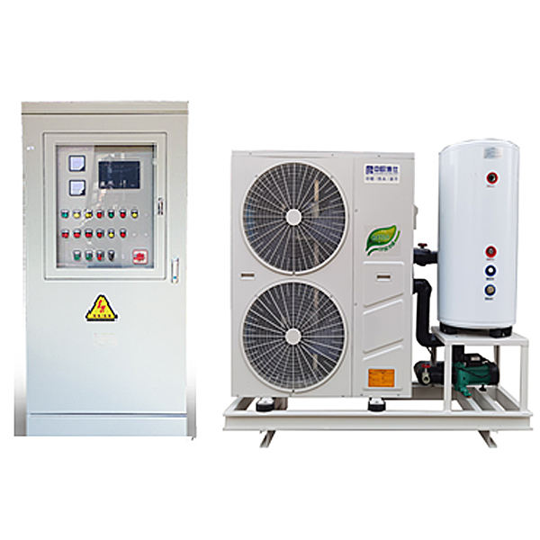
DYLR-DRB combined low temperature DC variable frequency air source heat pump training device
Release time:2024-06-17 18:34viewed:times
The combined low-temperature DC variable frequency *r source heat pump tr*ning device is a product developed in accordance with the requirements of the Ministry of Education's "Revitalizing the 21st Century Vocational Education Curriculum Reform and Textbook Construction Plan" and the teaching and tr*ning requirements of vocational education. It is suitable for the refrigeration and heating technology and heat pump technology teaching and tr*ning experimental tr*ning device for higher vocational colleges and vocational schools. Heat pump technology is one of the effective measures to recover and utilize low-level thermal energy. Researching and promoting heat pump technology is of great significance to energy conservation. With the development of refrigeration technology in recent years, heat pump technology has been increasingly widely used in China.
2. Technical performance
1. Input power: single-phase three-wire ~ 380V ± 10% 50Hz
2. Working environment: temperature -10℃ ~ +40℃, relative humidity <85% (25℃), altitude <4000m
3. Device capacity: less than or equal to 1.5kVA
4. Refrigerant: random
5. Heating capacity: 3kW
6. Weight: 200kg
7. Dimensions (approximately): 180cm×73cm×164cm
8. Safety protection: with leakage voltage, leakage current overcurrent protection device, safety meets national standards.
3. Features and functions
Air source host base: The tr*ning is made of high-quality industrial profiles, with beautiful appearance, corrosion resistance, high structural strength, solid structure, and beautiful shape.
1. The system unit is equipped with multiple protections such as high and low voltage protection system, overload protection, phase loss protection, and defrosting function to ensure the safe, reliable and stable operation of the system without affecting the teaching course.
2. The whole system adopts fully automatic intelligent control, which is easy to operate. The water temperature, water level, opening, closing and time can be freely set by the user. The whole machine adopts the automatic memory function of power f*lure, so there is no need to repeat the operation every time, which is convenient and practical.
3. Compressor: This device adopts a heat exchanger forged from high-quality copper parts, which has high heat exchange efficiency, safety and reliability. DC variable frequency compressor (jet enthalpy increase), internationally renowned brand
4. Insulated water tank: 2 tons, using brushed silver technology, combining fashion with technology, the equipment has a beautiful appearance, and the water tank is made of 304 st*nless steel, which is durable and not easy to corrode or damage.
5. Host: 5-15P, DC variable frequency ultra-low temperature type, the system adopts industrial *r source heat pump hot water unit, which is consistent with the actual industrial equipment, so that teaching can be integrated with practical applications. The outdoor host adopts thickened sheet metal p*nt type, which can withstand different experimental environments, work effectively for a long time, and will not rust or corrode.
6. The tr*ning device intuitively displays the system structure and working principle of the heat pump water heater. The heating cycle system structure and the m*n components can be clearly seen. The system is also equipped with an AC voltmeter, AC ammeter, temperature meter, and vacuum pressure gauge, so that the real-time working status of the entire heat pump system is clear at a glance.
7. Water pump: 1.1KW vertical booster pump,
8. Fan: two AC motors , power 245W
9. The host is wireless 4G, and the project is wireless 2G signal source
10. Wireless WiFi controller: 5.5-inch touch LCD controller microcontroller , PLC programmable design and control virtual simulation software:
This software is developed based on unity3d, with built-in experimental steps, experimental instructions, circuit diagrams, component lists, connection lines, power on, circuit diagrams, scene reset, return and other buttons. After the connection and code are correct, the three-dimensional machine tool model can be operated through the start/stop, forward motion, and reverse motion buttons . When the line is connected, the three-dimensional machine tool model can be enlarged/reduced and translated.
1. Relay control: Read the experimental instructions and enter the experiment. By reading the circuit diagram, select relays, thermal relays, switches and other components in the component list and drag and drop them into the electrical cabinet. The limiter is placed on the three-dimensional machine tool model. You can choose to cover the cover. Some component names can be renamed. Then click the connect line button to connect the terminals. After the machine tool circuit is successfully connected, choose to turn on the power and operate. If the component or line connection is wrong, an error box will pop up. The scene can be reset at any time.
2. PLC control: The experiment is the same as relay control, and the PLC control function is added. After the connection is completed, enter the program writing interface through the PLC coding button. Write two forward and reverse programs. There are 12 ladder diagram symbols in total. After writing, select Submit for program verification. After successful verification, turn on the power to operate. If there are component, line connection, and code errors, an error box will pop up. The scene can be reset at any time.
3. Single-chip microcomputer control: The experiment is the same as the relay control, with the single-chip microcomputer control function added. After the connection is completed, enter the programming interface through the C coding button, enter the correct C language code, submit the verification successfully, turn on the power to operate, and the component, line connection, and code errors will pop up a prompt error box, and the scene can be reset at any time.
11. Mobile remote APP: Software control, can control the temperature of the system online, read the flow opening number of the unit's refrigeration refrigerant in the optimal temperature system, and adjust the superheat and subcooling of the refrigeration unit. The left side of the text display interface displays the current unit's operating data in real time in the form of text. In the upper part of the right side of the interface, the communication information is displayed, including the communication role and the set value of the communication port and the display of the current communication status. In the lower part of the right side of the interface, "Data Information", it shows which data frame is currently received, the address of the received data frame, and other information. It has online and manual adjustment functions for upper computer adjustment:
1) Controllable settings: water tank temperature, compressor restart time, return water temperature, fan conversion temperature, defrost time, defrost cycle, defrost temperature, unit energy-saving control and automatic flow adjustment.
2) Temperature display: The controller detects the temperature of multiple points of the system at the same time to control the overcooling/overheating of the unit.
3) The minimum opening degree of the refrigerant flow of the refrigeration system can be set automatically. 2) Parameter control parameter setting: All temperature parameters, time parameters, control parameters, and other parameters related to control in the controller can be adjusted.
4) Automatic adjustment: The equipment has a power-off memory function when running to keep the current value unchanged.
5) Overcooling/heating control range: 2-15 degrees Celsius. The overcooling and overheating of the refrigeration host can be set by yourself to provide data for the design.
6) Current and voltage data
12. Control panel:
It adopts iron double-layer matte dense spray structure and high-quality acrylic panel. The panel is laser engraved with the process flow chart of the heat pump unit system. The process flow schematic diagram will never wear out, clear and three-dimensional. There are clear signs and corresponding indicator lights on the panel to facilitate students' analysis and observation.
Control part: AC power supply: Provides single-phase AC power required for the control panel and the heat pump unit, which can be controlled by the m*n power switch. It is equipped with a three-and-a-half-digital AC voltmeter and AC ammeter, which can indicate the input grid voltage, current, power, power factor, active power, no power, power
A, and experimental table control intelligent module: This module can control the working environment of the whole machine, determine the working stability of the system, protect the stability and safety of students during practical tr*ning, and cut off the m*n power supply at critical times.
1) The intelligent module can detect and monitor the voltage of the AC power supply of the device system. When measuring overvoltage, the device is overloaded and can collect the current value of the AC power supply of the monitored device. When measuring the overcurrent value, the device is overloaded and can collect the AC power temperature of the monitored device. When measuring overtemperature, the device is overloaded.
2) Software platform:
current, voltage temperature, and upload to the monitoring host or monitoring cloud platform through CAN/GSM communication. The monitoring host or cloud platform can determine the operating status of the monitored power supply, such as voltage, current, current and temperature.
3) The rated voltage of the working power supply is AC220V, the power consumption is normal monitoring state ≤2W alarm state ≤2.5W,
4) Monitoring alarm overvoltage (115%), undervoltage (80%) overcurrent, current (50~1000mA).
5) Temperature: 50-120 degrees, leakage alarm: 50-1000MA continuously adjustable, leakage alarm channel: 1 channel, temperature alarm: 4 channels.
6) Current detection channel: 1 channel, voltage detection channel: 3 channels.
7) Alarm mode: APP remote alarm contact capacity AC 220V/3A, DC 30V/3A,
8) Communication interface communication/GPRS communication (optional) effective communication distance ≤1km.
9) The system can be controlled by downloading APP software through the mobile phone, or the computer can monitor through the software,
10) Sensor : Current transformer and current transformer: use 2000:1. If the actual transformer and product configuration are different, the temperature sensor uses a 100K characteristic thermistor.
11) Function display: can display voltage, current, power
12) Interface software
13) Wireless sensor: Voltage: 3.6V. Standby current: 20MA. Alarm current output 250MA, low voltage alarm: 30 days, communication mode: GSM, receiving sensitivity: -129dBm, wireless standard
14), built-in wireless network signal transmission, can connect to 4G network, no need to increase communication cost
13, pipeline system: electric three-way adjustment, flow switch, copper filter, st*nless steel soft connection, national standard copper gate valve, national standard PPR-plated pipe, B1 grade fireproof rubber insulation
14, flow measurement: electromagnetic flowmeter can measure system water flow
B, experimental power intelligent safety control device
1. Features
When the intelligent control system detects leakage or electric shock, the intelligent control system disconnects in 0.1 seconds to ensure personal and property safety; the intelligent control system itself has a fault indicator light, and the user can judge the current fault status according to the fault indicator light of the intelligent control system, which is convenient for handling; the intelligent control system has a padlock function. When m*ntenance is required, it is locked at the padlock position to prevent others from powering on, and m*ntenance is safer. It can collect data from on-site output devices and upload them to the cloud through various IoT communication methods to achieve remote monitoring of local equipment.
2. Functions
Based on the IoT laboratory safe power intelligent control system, power data collection , statistics, storage, analysis, query, etc. can be performed. Use front-end data visualization technology to display real-time power data on the platform, and provide visualized power information query functions in the form of charts; use database technology to monitor the operation status of power equipment and lines in real time, and give timely warnings for abnormal conditions to prevent electrical fires; use power system fault location technology to timely discover and accurately locate power fault points, automatically generate fault reports, and assist users to rep*r power system faults as soon as possible; use power quality monitoring technology to analyze and evaluate power quality problems in real time, and provide customized governance solutions to help users obt*n high-quality electricity; use big data technology and industry mathematical models to count, analyze and mine basic power data, and explore energy-saving potential based on data, thereby providing energy efficiency optimization solutions. Meet the needs of visual, safe, reliable, high-quality and economical smart power modules for power management systems.
3. The intelligent control system for safe electricity use in laboratories based on the Internet of Things consists of an actuator and a network machine, and the technical parameters are as follows:
(1) Technical parameters of the actuator
(1) Number of poles: 3P+N
(2) Tripping characteristics: C (5-10) In D (10-14) In
(3) Rated current: In 6A, 10A, 16A, 20A, 25A, 32A, 40A, 50A, 63A
(4) Rated voltage: Ue AC 230V/400V
(5) Rated frequency f: 50Hz
(6) Rated short-circuit breaking capacity: Icu10kA
(7) Frame grade rated current: Inm63A
(8) Phase loss protection: Equipment burnout protection mode
(9) Leakage protection: Component damage protection mode
(10) Overload protection: Overcurrent burnout protection mode
(11) Short circuit protection: line touch protection mode
(12) Padlock protection: easy to m*nt*n and safe
(13) Over temperature protection: can monitor line temperature
(14) Over-voltage and under-voltage protection: prevent personal accidents and mechanical equipment damage
(15) 0.1 second disconnection in case of leakage or electric shock
(16) Fault indicator light, easy to check the working status
(17) Padlock function, more convenient for m*ntenance
(2) Network machine technical parameters
(1) Built-in STM32F103C8T6 m*n control chip
(2) External 8M passive crystal oscillator
(3) Use SP3485 as 485 communication chip
(4) 485 anti-surge protection
(5) Standard RS485 interface, can directly serial port equipment
(6) Intelligent data terminal, convenient to realize data transmission function
(7) Provide powerful central management software, convenient equipment management
(8) Provide convenient software upgrade and firmware update service
(9) Provide database data backup, convenient to view historical data
(10) Dimensions: 89mm*67.5mm*20.5mm
(11) Weight: 70g
(12) Power supply: AC220V
(13) Power consumption: 1.5W
(14) Operating temperature: -25℃ - +70℃
(15) Operating humidity: 95%
(16) Maximum downlink transmission rate of WiFi version: 64kbps
(17) Maximum uplink transmission rate of WiFi version: 32kbps
IV. Tr*ning projects
1. Knowledge and understanding of heat pump system
2. Tr*ning on start-up, operation, commissioning and protection technology of heat pump system
3. Detection and analysis of operating conditions and operating parameters of heat pump
4. Calculation and analysis of heating capacity and performance coefficient of heat pump
5. Setting and detection of heat pump system faults
6. Measuring COP of *r source unit


 Wechat scan code follow us
