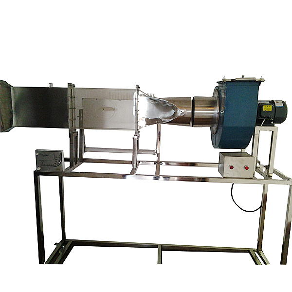
DYHGRG-22 Multifunctional Boundary Layer Training Device
Release time:2024-06-13 09:35viewed:times
Technical parameters:
1. Input power: three-phase AC380V±10% 50Hz, power 1.5KW.
2. Centrifugal fan parameters: *r volume 2200 m3/h, wind pressure 1000 Pa, power 1.5KW.
3. Local suction exhaust hood, transparent plexiglass material; experimental pipe diameter Φ160mm.
4. Pitot tube flowmeter with inclined tube micromanometer to measure flow rate: range -10-700pa.
5. 24-tube inclined tube differential pressure gauge to measure pressure distribution at each point of cylindrical specimen and wing specimen, length 800mm, with height displacement ruler.
6. Experimental *r duct, *r inlet section and *r outlet section are made of 304 st*nless steel, and the experimental section is made of transparent plexiglass. The experimental section can switch to install various specimens, and flange nuts are used to connect each other for easy disassembly.
7. Overall dimensions: 1700×500×1700mm, the appearance is a st*nless steel movable bracket with double brake wheels.
8. Virtual simulation software for electrical installation of building and intelligent building Designed based on unity3d, users can choose different sizes of interactive interface according to computer configuration, and can choose six levels of image quality. The model in the software can be rotated 360°, enlarged, reduced, and translated. There are assistant prompts during the use of the software, as follows: A. Wet alarm system 1. System overview: Overview of wet alarm system 2. Equipment recognition: It has the best viewing angle, equipment det*ls (displaying the introduction or parameters of the equipment), exercises (built-in 6 multiple-choice questions, with prompts for correct and wrong choices), schematic diagram (you can enter the equipment from the schematic diagram). The equipment includes: sprinkler, water flow indicator, signal butterfly valve, exhaust valve, fire alarm control, high pressure gauge, high-level water tank, Wia control cabinet, pressure regulating tank, flow switch, end water test device, dr*nage facilities, water pump connector, hydraulic alarm, delay, wet alarm, butterfly valve, check valve, fire pump, safety pressure regulating valve, fire water tank. 3. Principle display: Display the working principle of the wet alarm system, 3D animation demonstration, 3D model is semi-transparent, and the internal water flow can be seen. Equipped with exercise module (4 multiple-choice questions are built-in, and there are prompts for correct and wrong choices) 4. Design layout: There are multiple-choice questions and calculation questions, each of which is scored, and the correct answer and score are displayed after submission B. Gas fire extinguishing system 1. System overview: Overview of gas fire extinguishing system 2. Equipment recognition: There are optimal viewing angles, equipment det*ls (displaying the introduction or parameters of the equipment), exercises (8 built-in multiple-choice questions, and there are prompts for correct and wrong choices), and schematic diagrams (you can enter the equipment from the schematic diagram). The equipment includes: nozzles, HFC-227 storage bottles, bottle head valves, heptafluoropropane check valves, high-pressure hoses, gas check valves, safety valves, weighing alarms, electromagnetic starters, selection valves, smoke alarms, and fire alarm controllers. 3. Principle display: Display the working principle of the gas fire extinguishing system, 3D animation demonstrations, and 3D models are semi-transparent, and the internal gas can be seen. Equipped with a practice module (3 multiple-choice questions built in, with prompts for correct and incorrect choices) 4. Design layout: There are 6 multiple-choice questions, each with a score. The correct answer and score will be displayed after submission. C. Escape drill: Teaching is conducted in the form of fun games. Escape from the burning room within a limited time. Wrong choices will directly enter the score interface. Experimental purpose: 1. Learn how to measure the surface pressure distribution of an object when a fluid flows around it. 2. Through experiments, understand the surface pressure distribution of an actual fluid around a cylindrical fluid and compare it with the pressure distribution of an ideal fluid. 3. Learn how to measure the surface pressure distribution of a wing when a fluid flows around it. 4. Determine the surface pressure distribution of the wing at different angles of attack. Determine the boundary layer thickness at different cross-sections of the flat plate and the velocity distribution profile in the boundary layer. M*n configuration: multi-blade low-noise centrifugal fan, experimental visual wind tunnel, automatic damper adjustment, inclined tube micromanometer to measure front and rear resistance pressure difference and flow pressure difference, adjustable angle 24-tube micromanometer to measure pressure at each point of cylindrical specimen and wing specimen, movable vernier scale, st*nless steel Pitot tube movable device to test flat plate boundary layer, plexiglass cylindrical specimen, plexiglass wing specimen, movable st*nless steel bracket, etc.


 Wechat scan code follow us
