Shanghai Daiyu Education Equipment Manufacturing Co., Ltd.
Language:


| project | Experimental teaching of basic theory and professional courses |
| Experimental teaching | 1. Determination of the total heat transfer coefficient K of three types of heat exchanger devices: tube, sleeve and plate. |
| Practical tr*ning function | Operational tr*ning content |
| Device function |
1. Operation tr*ning on start-up, shutdown and operation of the heat exchanger 2. Operation tr*ning on automatic adjustment of the cold fluid outlet temperature 3. The influence of the relative flow direction of hot and cold fluids on the heat exchange effect (switching between countercurrent and parallel flow) 4. The flow pattern of the fluid (Flow rate) influence on heat exchange effect 5. Operation of series and parallel connection of tube heat exchangers. 6. The influence of non-condensable gas in steam on heat transfer effect. 7. Determination of heat transfer coefficient K. |
| Prepare to drive |
1. Read and describe the process flow diagram 2. Be familiar with the site numbers, functions, working principles and usage methods of on-site devices and m*n equipment, instruments and valves 3. Develop an operation plan as required 4. Check each equipment, pipeline, Whether the valve is in normal driving condition 5. Introduce public utilities (water, electricity, steam) and ensure normal operation 6. Power on the device and check whether the status of each instrument is normal; test run the equipment |
| drive |
1. Follow the correct driving steps and adjust the *r flow and steam pressure to the specified values. 2. Be able to perform heat exchanger switching operations. |
| normal operation |
1. Able to change the *r flow and steam pressure to specified values and re-establish normal operation. 2. Inspect various temperatures, pressures, and flows as required and keep records, and be able to judge whether each indicator is normal in a timely manner. 3. Inspect moving equipment (blower) as required. 4. Observe the operating status of the heat exchanger during normal operation, and point out factors that may affect its normal operation. 5. Able to adjust the *r outlet temperature according to normal operation. 6. Able to measure the total temperature of the heat exchanger. Heat transfer coefficient |
| parking |
1. Stop the vehicle according to normal parking procedures. 2. Check the status of each equipment, valves and steam package after parking, and make records after confirmation. |
| Accident handling |
1. Be able to observe and analyze system operation abnormalities caused by low steam pressure and restore them to normal operating conditions 2. Be able to observe and analyze system operation abnormalities caused by the presence of non-condensable gas in the heat exchanger and restore them to normal operating conditions 3. Will observe and analyze abnormal phenomena caused by f*lure to remove condensate in the heat exchanger in time and restore it to normal operating conditions |
| Equipment m*ntenance |
1. The starting, stopping, normal operation and d*ly m*ntenance of the blower 2. The structure, working principle, normal operation and m*ntenance of the heat exchanger 3. The location, type and structure of the m*n valves (steam pressure adjustment, *r flow adjustment, steam trap) , working principle, normal operation and m*ntenance |
| control instrument |
1. Measurement principles of temperature, flow and pressure sensors ; use of temperature and pressure display instruments and flow control instruments. 2. Control the normal use of the actuator inverter and regulating valve. |
| software |
1. Familiarity, understanding and use of upper monitoring platform software 2. Mechanical tr*ning safety education virtual simulation software: This software is developed based on unity3d. The software adopts the form of three-dimensional roaming, and can control movement through the keyboard and the mouse to control the lens direction. It is equipped with mechanical Safety distance experiment, mechanical safety protection device experiment, and basic assessment of mechanical safety protection design. During the experiment, the three-dimensional roaming screen uses arrows and footprints to prompt moving to the experimental location. The circle around the mechanical object shows the working radius. The experimental process is accompanied by a three-dimensional robot. dialog box reminder. A. The content of the mechanical safety distance experiment includes the safety distance experiment to prevent upper and lower limbs from touching the danger zone (divided into two fence heights and opening sizes). After selecting to enter, GB23821-2009 "Mechanical Safety to Prevent Upper and Lower Limbs from Touching the Danger Zone" pops up in front of the camera. "Safe Distance" requirements, error demonstration: The experimental process is that after the human body enters the working radius of the mechanical object and is injured, the red screen and voice prompts that the human body has received mechanical damage, and returns to the original position and conducts the next experiment. The last step is the correct approach. B. Mechanical safety protection device experiments are divided into safety interlock switches, safety light curt*ns, safety mats, safety laser scanners and other protection device experiments. Optional categories (safety input, safety control, safety output, others), manufacturers, products List (safety interlock switch, safety light curt*n, safety mat, safety laser scanner, safety controller, safety relay, safety guardr*l). There is a blue flashing frame reminder at the installation location. Experimental process: select the safety guardr*l and install it, select the safety interlock switch (or select the safety light curt*n, safety mat, safety laser scanner) and install it, select the safety controller and install it in the electrical control box , select the safety relay and install it in the electrical control box, click the start button on the electrical control box. If you enter a dangerous area, the system will sound an alarm and the mechanical object will stop working. Select the reset button on the electrical control box to stop. C. The basic assessment of mechanical safety protection design requires the completion of the installation of the mechanical safety system, and the correct installation of safety guardr*ls, safety interlock switches, safety light curt*ns, safety mats, safety laser scanners, safety controllers, safety relays, 24V power supplies, signal lights and Emergency stop button. The assessment is divided into ten assessment points. Some assessment points have 3 options, which are freely chosen by the students. After selecting the final 10 assessment points, submit for confirmation, and the system will automatically obt*n the total score and the score of each assessment point. . D. The software must be on the same platform as a whole and must not be displayed as separate resources. At the same time, the VR installation package of this software is provided to customers to facilitate users to expand into VR experiments. VR equipment and software installation and debugging are not required. |
| category | Material name | Specifications and models | quantity | Remark | |
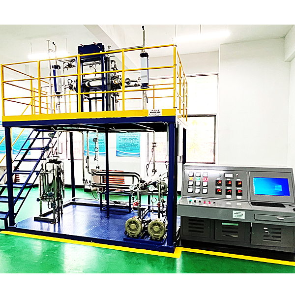
| 1. M*n body of the equipment: object part: length × width × height: 3700 × 2000 × 3500mm. The whole machine adopts a steel installation frame (two-layer design, the first floor is convenient for operation, m*ntenance, and access, and there is a safety ramp leading up to the second floor. And there are guardr*ls and anti-slip pattern boards) | |||||
| moving equipment | fan | High-efficiency vortex *r pump, power, 750W, maximum flow 100m2/h | 3 units | ||
| Oil-free lubricated compressor | Air compressor: 0-0.8Mpa, exhaust volume 0-0.0 12M3/min | 1 set | |||
| centrifugal pump | CHLF2-20/power 0.37KW/flow 2M3/H | 1 set | |||
| Static equipment (φ159 double parallel row-tube heat exchanger) | φ159 double parallel row tube heat exchanger | φ189×1300mm st*nless steel tube heat exchanger (heat exchange area 1.0m3) | 2 units | ||
| Static equipment (φ108 single row tube, casing, plate type-cold *r-hot *r system) | φ108 single tube heat exchanger | φ144×1200mm st*nless steel tube heat exchanger (heat exchange area 0.76m3) | 1 set | ||
| St*nless steel sleeve heat exchanger | The inner heat exchange tube is made of st*nless steel, and the outer heat exchange tube is made of st*nless steel with an aluminum silicate insulation cotton insulation layer (heat exchange area 0.5m3) | 1 set | |||
| St*nless steel plate heat exchanger | St*nless steel (heat exchange area 0.5m3) | 1 set | |||
| steam distributor | With connecting pipes such as safety valves and intermediate management valves (φ108×1000mm st*nless steel) | 1 set | |||
| Fully automatic steam generator | Heating power 6KW, maximum steam pressure 0.4Mpa | 1 set | |||
| Static equipment (φ159 single tube heat exchanger, water-hot *r system) | φ159 single tube heat exchanger | φ189×1200mm st*nless steel tube heat exchanger (heat exchange area 0.8m3) | 1 set | ||
| St*nless steel water tank | 450×500×600mm 304 st*nless steel water tank | 1 set | |||
| 2. Detect control parameters | |||||
| variable | testing facility | Display control instrument and model | quantity | control mechanism | |
| Detect control parameters | Cold and hot fluid fan flow detection and control | Orifice flow meter + diffused silicon differential pressure transmitter Accuracy: 1.5%FS |
Intelligent flow totalizer Yudian AI-708H |
2 | Frequency converter |
|
Intelligent regulator Deutsche Electric AH7009 |
|||||
| φ159 double parallel row tube heat exchanger shell side steam pressure | Ceramic pressure transmitter pressure transmitter and national standard pressure pointer gauge | regulating valve | 2 | Steam pressure reducing valve | |
| φ159 double parallel row tube heat exchanger cold fluid inlet and outlet temperatures | PT100 thermal resistance (4) | Intelligent 6-channel inspection recorder D76009 | 4 | ||
| φ114 single row tube, casing, plate type - cold *r-hot *r system heat exchanger cold and hot fluid inlet and outlet temperatures | PT100 thermal resistance (2) | Intelligent 6-channel inspection recorder D76009 | 2 | ||
| Heat exchanger steam drum outlet temperature | PT100 thermal resistance (2) | Intelligent 6-channel inspection recorder D76009 | 1 | ||
| control actuator | *Mitsubishi inverter | FR-D540 frequency converter, specifications: (0-50) Hz/0.75KW | 2 units | ||
| The electromagnetic valve | St*nless steel, φ15 mm normally open | 4 units | |||
| The electromagnetic valve | St*nless steel, φ15 mm normally closed | 2 units | |||
| Steam pressure regulating valve | DN20dg15 | 2 units | |||
| pressure regulating valve | DN15,0-1MPa | 2 | |||
| Ball valve, globe valve, trap, etc. | St*nless steel | a batch | |||
| computer control | Communication network converter | RS485/232 communication converter | 1 set | ||
| Operator station upper monitoring computer | Lenovo dual-core 2.0G, memory 1GDDR2, hard drive 250G, optical drive, mouse, keyboard, 3-year warranty, monitor: 17" LCD, nationwide warranty; operating system: genuine WINDOWS XP. | 1 set | |||
| 3. Intelligent instrument electrical console and computer control console | |||||
| Smart instrument electrical console | On-site intelligent instrument electrical console (including embedded industrial control machine): The leakage protection *r switch and current leakage protector are installed in the steel spray mold to fully consider personal safety protection; at the same time, each group of strong current output has a knob switch control , ensuring equipment safety and convenient operation and control; equipped with phase-separated indicator lights, switching power supplies, contactors, solid-state relays, self-locking switches, plastic copper wires, rubber sheathed wires, shielded wires, aluminum alloy wire troughs, etc. | ||||
| 4. Upper-level monitoring software for smart instruments: 1. MCGS industrial control configuration software; 2. Upper-level monitoring software (using industrial control configuration software as the platform software) | |||||
 Wechat scan code follow us

24-hour hotline+86 18916464525

Phone18916464525
ADD:Factory 414, District A, No. 6, Chongnan Road, Songjiang Science and Technology Park, Shanghai ICP: Sitemap