Shanghai Daiyu Education Equipment Manufacturing Co., Ltd.
Language:


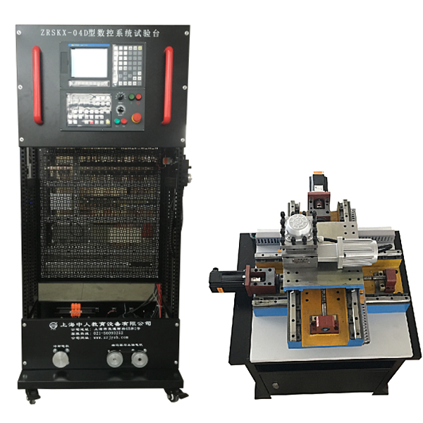


product components
CNC lathe tr*ning equipment consists of a CNC system, machine tool electrical control interface board, spindle frequency conversion and speed regulation experimental board, AC servo drive and servo motor , input and output module, four-station tool holder, principles and wiring of low-voltage electrical components, programming and Mechanical and other components.
Product features:
☆Do our best to show the essence of the CNC system to users in the most intuitive way, so that users can participate to the maximum extent and g*n in-depth experience to achieve a comprehensive effect.
☆The convenient disassembly design allows users to receive on-site tr*ning in mechanical, electrical and other aspects, leaving a deep impression on them.
☆Involves rich content; CNC system, servo unit, logic control, low-voltage electrical appliances, motors...
The tr*ning bench is equipped with: 1 automatic tool holder, 1 set of spindle motor and encoder, 1 cooling pump, 2 servo motors, 1 simulated lathe workbench (two coordinates), limit switch, machine tool zero point, precision optics Displacement detection unit (grating ruler), etc.
Experimental bench technical parameters:
1. Input power supply: AC380V (three-phase four-wire system), 50HZ
2. 36 fault assessment items
3. Working environment: temperature -200C~400C
4. Overall machine capacity: ≤3kVA;
5. Electrical control unit size: length × width × height (mm) = 800mm × 600 mm × 1800 mm;
6. Simulation lathe workbench unit size: length × width × height (mm) = 660mm × 660mm × 370mm;
7. Teacher’s computer is equipped with three-dimensional simulation courseware to assist teaching
Basic module: This courseware can be programmed through the built-in controller programming interface and written into a virtual controller to control the 3D simulation model . Can simulate and control no less than 20 3D simulation models. Virtual controller status can also be monitored and a reset function can be used to reset a component if it becomes stuck. It has step-by-step teaching function, teaching from easy to difficult. CNC three-dimensional module: Based on the real CNC machine tool electrical component model, it is equipped with a simulated servo driver and VFD controller. It can set parameters for the servo and reflect it on the simulation model. It can simulate the FANUC Oi series system and pass the mechanical transmission part of the machine tool. Carry out troubleshooting of the electrical control part and process the workpiece, and be able to connect, delete, clear connections, restore connections and select wire specifications between electrical components of logic circuits. The CNC panel is developed according to the FANUC 0i series model, which can Corresponding machine tool problems can be rep*red by modifying relevant parameters. The experiment is equipped with 2D circuit drawings, plc wiring drawings, PLC schematic drawings, pneumatic schematic drawings, hydraulic schematic drawings, CNC flow chart and PLC IO allocation table. By selecting a terminal in the circuit diagram, you can quickly find the corresponding terminal in the three-dimensional model. The system simulates the circuit current flow according to the actual connection situation. The modules are respectively equipped with connection faults, component faults, parameter faults, hardware faults, mechanical faults, etc. , and can also disassemble and assemble the machine tool. Equipped with professional cases and resources. Machine tool machinery 3D module: It has a 3D parts library and text descriptions of parts functions and applications. It can realistically and vividly complete 3D animation demonstrations of more than a dozen kinds of mechanism movements. It can complete assembly tr*ning of more than a dozen kinds of mechanisms and provide correct mechanical mechanism components. The assembly sequence list is provided for students to use for practical operations on the computer, and can automatically complete the assembly and assembly and disassembly process explosion diagram demonstration of more than a dozen types of mechanical planar mechanisms. It has functions such as virtual disassembly and assembly of mechanical mechanisms, animation demonstration, explosion diagram display, saving and reading assembly records, single part display, and degree of freedom calculation. Mechanical installation module: Based on C# and JS language programming design, users can choose different interactive interface sizes according to computer configuration, with six image quality levels including smooth image quality, medium image quality, and perfect image quality. More than ten types of shafting mechanisms, including gear shafting and worm shafting, can be selected for installation, disassembly, assembly, parts measurement, and assessment. There are smart reminders during the steps of parts disassembly and assembly. The models in the module are all 3D models, produced by 3Dmax, and have been rendered and polished to make the models look the same as real parts. There is a non-standard parts library, Standard parts library and measurement tool library for disassembly and assembly selection. It is equipped with electronic experiment assessment questions and instructions that integrate the purpose, steps, and requirements of the experiment . When using the assessment function, questions are randomly generated for students to answer, and assessment scores are given when students finish answering the questions. The model can be rotated in all directions, zoomed in, and zoomed out to view its det*ls. The bidding site will provide color pictures of each module of this courseware with the official seal of the manufacturer, a demonstration video of each module of this courseware, and a parameter confirmation statement issued by the manufacturer that it can fully meet all parameters of this courseware. Scoring will be based on the parameter satisfaction of the demonstration video, and bids without a parameter confirmation statement will be deemed invalid.
Basic Experimental Internship Project
Experiment 1 Power supply control of CNC lathe electrical comprehensive experimental device
Experiment 2 CNC system operation and interface experiment
Experiment 3 Frequency converter speed regulation experiment (system control)
Experiment 4 Four-station automatic tool rest experiment
Experiment 5 X-axis servo motor drive control experiment
Experiment 6 Z-axis servo motor drive control experiment
Experiment 7 Two-coordinate positive and negative overtravel limit and zero point experiment
Experiment 8: Handwheel (hand-operated pulse generator) experiment
Experiment 9: Thread processing experiment controlled by lathe CNC system
Experiment 10 CNC lathe system communication experiment
Experiment 11 CNC lathe PMC programming and connection experiment
Experiment 12 CNC lathe electrical comprehensive installation and wiring experiment
Experiment 13: Design of PMC user program
Experiment 14 Debugging of PMC user program
Experiment 15 CNC lathe NC parameter debugging (1)
Experiment 16 CNC lathe NC parameter debugging (2)
Experiment 17 CNC lathe screw rod backlash compensation experiment
Experiment 18 CNC lathe screw pitch compensation experiment
Experiment 19 CNC lathe geometric accuracy detection and adjustment experiment
1. Equipment overview
CNC lathe tr*ning equipment is suitable for CNC machine tool assembly, adjustment and m*ntenance skills competitions in vocational colleges and teaching and tr*ning in CNC assembly, adjustment and m*ntenance majors, CNC machining majors, and mechatronics majors in vocational schools. The equipment is based on the CNC m*ntenance of vocational schools. Professional teaching characteristics, combined with the actual needs of the enterprise and the requirements of job skills and process specifications, it is a practical tr*ning equipment with production functions and learning functions. The equipment adopts a modular structure and can complete the electrical installation and adjustment of CNC machine tools through different combinations. , system debugging, mechanical geometric accuracy testing and m*ntenance of CNC machine tool functional components and other practical tr*ning projects, which meet the needs of enterprises for this type of talent, and are also suitable for the professional skills appr*sal of CNC assembly and adjustment workers.
2. Equipment function description
The CNC lathe tr*ning equipment consists of an electrical control unit, an electrical installation tr*ning unit, a simulated lathe workbench, etc.
1. Function description of electrical control unit:
The electrical control unit m*nly includes a CNC system, feed drive, spindle unit, PMC unit, tool rest control circuit, cooling control circuit, interface unit, protection circuit, power circuit, etc. This unit cont*ns the complete electrical control part of the CNC lathe, embedded with the CNC machine tool intelligent assessment system, and the interface conversion unit, which can be directly connected to the CNC machine tool functional components for real electrical debugging and m*ntenance tr*ning; it can also be connected through the interface The conversion unit and the electrical installation tr*ning unit are connected to complete the debugging of the functional components of the CNC machine tool. The vertical structure conforms to the real CNC electrical installation environment, the device layout is consistent with the actual machine tool, and complies with the GB/T5226.1-1996 standard, allowing skill tr*ning to be more in line with actual job requirements.
It has the function of fault diagnosis and m*ntenance assessment of CNC lathes, and can set 36 typical electrical faults of CNC lathes. The assessment system adopts an intelligent assessment method and has the function of networking. Faults can be set through the computer or on the intelligent assessment terminal. Students analyze the fault phenomenon and enter the corresponding fault code on the assessment terminal to troubleshoot. Multiple devices can be connected to the network through the wireless network and the host computer to centrally manage teacher login, student exams, fault question banks, and separate settings. And can analyze, evaluate, archive, and print test results.
2. Function description of electrical installation unit:
The electrical installation tr*ning unit is m*nly designed to meet the needs of repeated tr*ning of CNC machine tool electrical installation skills. It includes a PMC interface unit, tool rest control circuit, lubrication control circuit, cooling control circuit, interface unit, protection circuit, power circuit, etc. The electrical installation board adopts a mesh plate structure that can be used repeatedly, and is connected through the interface conversion unit and the electrical control unit to complete the debugging of the functional components of the CNC machine tool.
The power supply part is equipped with a leakage switch and a phase loss protection circuit. When leakage, short circuit, or phase loss occurs, the equipment protection circuit will automatically act.
3. Description of functional component units of CNC machine tools:
The functional component unit of the CNC machine tool is a representative two-axis precision simulation lathe workbench. This component adopts the same mechanical structure as the real machine tool. It is m*nly designed to solve the difficulty of practical tr*ning in CNC machine tool mechanical disassembly and assembly projects. , in traditional CNC machine tool mechanical disassembly and assembly tr*ning, real machine tools are generally used for mechanical disassembly and assembly tr*ning. The teaching cost is high, the loss is large, and the heavy machine tool components lead to practical problems such as difficulty in disassembly and assembly, and difficulty in accuracy recovery. It is difficult to Carry out disassembly and precision testing tr*ning for all employees. This simulated lathe workbench refines the core skills of real machine tools in the disassembly and assembly process, that is, students m*nly disassemble and assemble transmission components, such as ball screws, linear guides, and couplings. machine, servo motor, etc. This equipment integrates these components into a simulated lathe workbench for practice, which not only saves costs, but also tr*ns core skills. In order to ensure accuracy and rigidity, the overall simulated lathe workbench module is of high quality. The rigid cast iron structure is made of resin sand and has been aged to ensure the accuracy of long-term use. The guide r*l uses linear guide r*ls, and the linear guide r*l installation uses the same pressure block structure as the real machine tool installation for fixation; the bearings use p*rs of angular contact bearings; The structure is modular and equipped with pulleys, which can move freely. It can complete the disassembly and assembly tr*ning of screws, linear guides, and screw brackets in mechanical transmission components, as well as precise precision such as guide r*l parallelism, str*ghtness, and biaxial verticality. Practical tr*ning in inspection technology, complete tr*ning in core skills of electromechanical joint debugging and mechanical assembly of CNC machine tools, and complete practical tr*ning projects such as pitch compensation and backlash compensation.
3. Simulation lathe workbench parameters:
Guide r*l form: imported TBI brand linear r*l
Screw type: imported TBI brand 1605 ball screw
X, Z stroke: 300×300 mm
Electric tool holder: 4 stations
Positioning accuracy: 0.01 mm
Spindle motor: Omron 0.75KW variable frequency stepless speed regulation 50-3000 rpm
 Wechat scan code follow us

24-hour hotline+86 18916464525

Phone18916464525
ADD:Factory 414, District A, No. 6, Chongnan Road, Songjiang Science and Technology Park, Shanghai ICP: Sitemap