Shanghai Daiyu Education Equipment Manufacturing Co., Ltd.
Language:


This device is based on relevant national occupational standards and industry standards, combined with " CNC technology and its application", " Mechanical manufacturing technology", "Mechanical and electrical equipment installation and m*ntenance", "Mechanical assembly", "Mechanical equipment assembly" of various vocational schools and technical colleges It is developed for the tr*ning goals of majors such as "automatic control" and "automatic control". It m*nly cultivates students' skills in reading and drawing assembly drawings and parts drawings, basic benchwork operations, parts and mechanism assembly processes and adjustments, and assembly quality inspection. Improve students' employability in front-line process assembly and implementation, mechanical and electrical equipment installation, debugging, m*ntenance and rep*r, mechanical processing quality analysis and control, grassroots production management and other positions in machinery manufacturing enterprises and related industries.
2. Product features
Strong practicality: Set various practical work tasks according to relevant national occupational standards, industry standards and job requirements, with professional practice activities as the m*n line, and truly improve students' hands-on skills and employability through "learning by doing".
Wide Applicability: Designed based on the basic work processes of fitter operations, assembly, measurement and adjustment, and quality inspection in mechanical assembly and adjustment technology, it can meet the needs of practical tr*ning, engineering tr*ning, and vocational skills competitions.
Modular design: composed of a variety of mechanical components, such as: two-dimensional worktable, multi-stage gearbox, intermittent rotary worktable, gear reducer and punch mechanism, etc. Each component can be tr*ned as an independent module, or each component can be combined into a comprehensive mechanical system for tr*ning.
Strong comprehensiveness: Cultivate students' comprehensive abilities such as mechanical drawing recognition, selection and use of commonly used tools and measuring tools, mechanical parts and mechanism processes and adjustments, and assembly quality inspection.
3. Technical performance
Input power: single-phase three-wire ~ 220V±10% 50Hz
1 AC reduction motor : rated power 90W, reduction ratio 1:25
Overall dimensions ( tr*ning table ): 1800mm×700mm×825mm
Equipment weight: 600kg
Safety protection: With current type leakage protection, safety meets national standards
4. System composition and functions
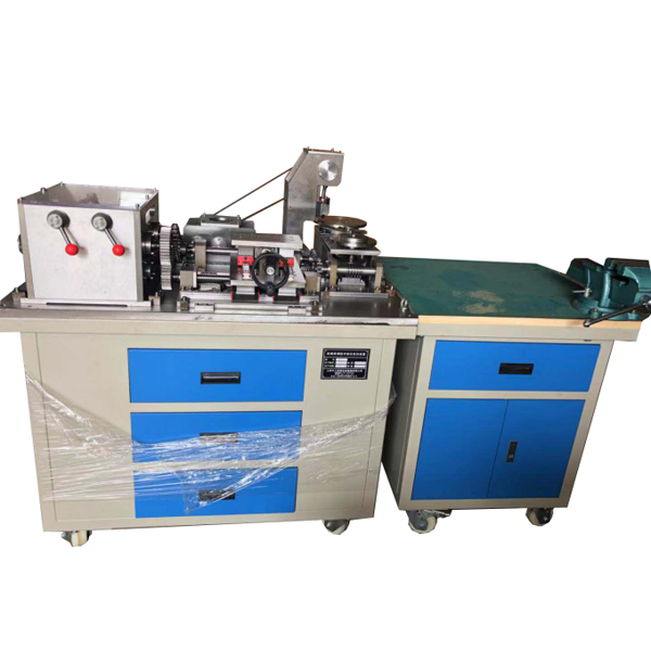
This device m*nly consists of a tr*ning platform, power source, mechanical assembly and adjustment objects ( mechanical transmission mechanism , multi-stage gearbox, two-dimensional workbench, gear reducer, intermittent rotary workbench, punch mechanism, etc.), assembly and adjustment tools, and commonly used measuring tools composed of other parts.
1. Practical tr*ning platform: It adopts an iron double-layer matt dense pattern spray-plastic structure, including an operating area and a mechanical assembly and adjustment area. The operating area is m*nly composed of solid wood tabletops, rubber pads, etc., which are used for benchwork processing and assembly of various mechanical parts; the mechanical assembly and adjustment area uses a casting operating table, on which students can install and adjust various mechanical mechanisms.
2. Mechanical transmission mechanism: It is m*nly composed of transmission mechanisms such as timing belts, ch*ns, gears, and worms. Through installation, adjustment, and testing on the platform, students will master the assembly and adjustment skills of mechanical transmission mechanisms.
3. Multi-stage gearbox: It has a dual-shaft three-stage variable speed output, one of which has a forward and reverse function, and the top is protected by plexiglass. It is m*nly composed of box body, gear, spline shaft, spacer sleeve, key, angular contact bearing, deep groove ball bearing, circlip, end cover, manual shift mechanism, etc. It can complete the assembly process tr*ning of multi-stage gearbox.
4. Two-dimensional workbench: m*nly composed of ball screws, linear guides, table tops, pads, bearings, supports, end covers, etc. It is divided into two layers, the upper layer is manually controlled, and the lower layer is controlled by a multi-stage gearbox through gear transmission to realize round-trip operation of the worktable. The worktable is equipped with a travel switch to realize the limit protection function; it can complete linear guide r*ls, ball screws, and two-dimensional Practical tr*ning on workbench assembly process and accuracy testing.
5. Gear reducer: M*nly composed of spur gears, angular contact bearings, deep groove ball bearings, brackets, shafts, end covers, keys, etc., which can complete the assembly process tr*ning of the reducer.
6. Intermittent rotary table: M*nly composed of four-groove sheave mechanism, worm gear, thrust ball bearing, angular contact bearing, table, bracket, etc. The multi-stage gearbox is indexed through ch*n drive, gear drive, worm gear drive and four-grooved sheave mechanism to achieve intermittent rotation function; it can complete the assembly and adjustment tr*ning of worm gears, four-grooved sheaves, bearings, etc.
7. Punch mechanism: It is m*nly composed of crankshaft, connecting rod, slider, bracket, bearing, etc. It cooperates with the intermittent rotary workbench to realize the simulation of the pressing function and complete the assembly process tr*ning of the punch mechanism.
8. Power source: Equipped with AC reduction motor, speed regulator, power control box, etc. to provide power source for the mechanical system. The power control box has a speed-regulating motor power interface and a travel switch interface.
9. Assembly and adjustment tools: M*nly including tool set (55 pieces), bench vise, marking plate, puller, round nut wrench, circlip pliers, copper rod, ch*n cutter, etc. The set of tools consists of a tool box, hexagonal wrench, dead wrench, adjustable wrench, file, tap, reamer, gauge, sample punch, hammer, die, die holder, screwdriver, bow saw, needle-nose pliers, vise, etc.
10 Commonly used measuring tools: m*nly composed of vernier calipers, vernier universal angle rulers, square rulers, lever dial indicators, micrometers, feeler gauges, depth vernier calipers, etc.; by using measuring tools for measurement, students can master the use of commonly used measuring tools and master mechanical assembly. detection methods, etc.
11. Mechanical assembly and benchwork assembly virtual simulation software
Using 3D virtual simulation technology and AVI video playback method, the interface is vivid and beautiful, easy to learn and use, which can increase students' interest in learning and deepen students' understanding and application of knowledge. Through the three-dimensional disassembly and assembly video animation, the disassembly and assembly process of the gearbox, clutch worm transmission mechanism, gear reducer, intermittent rotary table, punch mechanism, power source, feeding mechanism and other modules are vividly displayed. The following functions can be achieved:
Basic knowledge and introduction to fitter assembly technology
The structure and working principle of the m*n components of fitter assembly technology
Virtual disassembly and assembly of gearbox, 3D animation video explanation and demonstration
Virtual disassembly and assembly of clutch worm gear mechanism, 3D animation video explanation and demonstration
Virtual disassembly and assembly of gear reducer, 3D animation video explanation and demonstration
Virtual disassembly and assembly of intermittent rotary worktable, 3D animation video explanation and demonstration
Virtual disassembly and assembly of punch mechanism, 3D animation video explanation and demonstration
Virtual disassembly and assembly of power source, 3D animation video explanation and demonstration
Virtual disassembly and assembly of the feeding mechanism, 3D animation video explanation and demonstration
12. Mechanical tr*ning safety education virtual simulation software (demo and copyright certificate provided): This software is developed based on unity3d and can be deployed on the cloud server or used in the local environment. The software adopts the form of three-dimensional roaming and can be controlled through the keyboard. , the mouse controls the direction of the lens, and is equipped with mechanical safety distance experiments, mechanical safety protection device experiments, and mechanical safety protection design basic assessments. When the experiment is in progress, the three-dimensional roaming screen uses arrows and footprints to prompt you to move to the experimental location, and circles around the mechanical objects are displayed. Working radius, the experimental process is accompanied by a dialog box reminder of the three-dimensional robot.
A. The content of the mechanical safety distance experiment includes the safety distance experiment to prevent upper and lower limbs from touching the danger zone (divided into two fence heights and opening sizes). After selecting to enter, GB23821-2009 "Mechanical Safety to Prevent Upper and Lower Limbs from Touching the Danger Zone" pops up in front of the camera. "Safe Distance" requirements, error demonstration: The experimental process is that after the human body enters the working radius of the mechanical object and is injured, the red screen and voice prompts that the human body has received mechanical damage, and returns to the original position and conducts the next experiment. The last step is the correct approach.
B. Mechanical safety protection device experiments are divided into safety interlock switches, safety light curt*ns, safety mats, safety laser scanners and other protection device experiments. Optional categories (safety input, safety control, safety output, others), manufacturers, products List (safety interlock switch, safety light curt*n, safety mat, safety laser scanner, safety controller, safety relay, safety guardr*l). There is a blue flashing frame reminder at the installation location. Experimental process: select the safety guardr*l and install it, select the safety interlock switch (or select the safety light curt*n, safety mat, safety laser scanner) and install it, select the safety controller and install it in the electrical control box , select the safety relay and install it in the electrical control box, click the start button on the electrical control box. If you enter a dangerous area, the system will sound an alarm and the mechanical object will stop working. Select the reset button on the electrical control box to stop.
C. The basic assessment of mechanical safety protection design requires the completion of the installation of the mechanical safety system, and the correct installation of safety guardr*ls, safety interlock switches, safety light curt*ns, safety mats, safety laser scanners, safety controllers, safety relays, 24V power supplies, signal lights and Emergency stop button, the assessment is divided into ten assessment points. Some assessment points have 3 options, which are freely chosen by the students. After selecting the final 10 assessment points, submit for confirmation, and the system will automatically obt*n the total score and the score of each assessment point. .
D. The software must be on the same platform as a whole and must not be displayed as separate resources.
Teacher teaching design system (providing demonstration and copyright certificate): This software is developed based on unity3d, with optional 6-level image quality. It is equipped with the design and virtual disassembly and assembly of reducers and shafting structures, the design and simulation of common mechanical mechanisms, and an institutional resource library. , a typical mechanical mechanism (virtual disassembly and assembly of a gasoline engine), the software is a whole software and cannot be individual resources.
A. Reducer design and virtual disassembly interface can choose worm gear bevel gear reducer, two-stage expanded cylindrical gear reducer, bevel cylindrical gear reducer, coaxial cylindrical gear reducer, bevel gear reducer, and one-stage cylindrical gear reducer. Gear reducer.
Worm and bevel gear reducer: After entering the software, the assembly content is automatically played, and each step in the video has text explanations.
Two-stage expandable cylindrical gear reducer: After entering the software, the content is played in the form of a video. The video content should include: part name (scan the QR code to see the name of the part), disassembly and assembly demonstration (including disassembly and assembly), virtual disassembly Installation (including overall, low-speed shaft, medium-speed shaft, high-speed shaft, box cover, box seat)
Conical cylindrical gear reducer, coaxial cylindrical gear reducer, bevel gear reducer, first-level cylindrical gear reducer: click to enter and automatically jump to the edrawings interface. The models are all three-dimensional models. Click on the component to display the component name. , can rotate, enlarge, reduce and translate 360° in all directions. At the same time, the entire reducer can be disassembled and assembled through the moving parts function. At the same time, the home button can be selected to return to the original state of the reducer. The bevel gear reducer and the first-stage cylindrical gear reducer have added the function of inserting a cross section, and the cross section can be freely dragged to observe the internal structure of the reducer.
B. Shaft structure design and virtual disassembly and assembly interface optional parts recognition, disassembly and assembly demonstration, and actual operation.
1. Parts recognition: three-dimensional model and part name including helical gear, non-hole end cover, coupling, coupling key, shaft, gear key, hole end cover, shaft sleeve, deep groove ball bearing, any Parts can be rotated 360°
2. Disassembly and assembly demonstration: There are 2 built-in cases. When you move the mouse to a cert*n part position (except the base and bearing seat), the part will automatically enlarge and the part name will be displayed. There are disassembly and assembly buttons, and the function will be automatically controlled by the software. Complete the disassembly and assembly of the shaft system structure. All three-dimensional scenes can be rotated, enlarged, reduced and translated 360° in all directions.
3. Practical operation: The three-dimensional parts are neatly placed on the table. The students manually select the corresponding parts and move them to the shaft system structure. The parts can be installed only when they are placed in the correct order and in the correct position. There is a restart button to facilitate students to restart. Conduct virtual experiments. When you move the mouse to a cert*n part location (except the base and bearing seat), the part will automatically enlarge and the part name will be displayed.
C. Common mechanical mechanism design and simulation, optional hinge four-bar mechanism design and analysis, I\II type crank rocker mechanism design and analysis, offset crank slider mechanism design and analysis, crank swing guide rod mechanism design and analysis, hinge Four-bar mechanism with integrated trajectory, eccentric linear-acting roller push rod cam , and centering linear-acting flat-bottomed push rod cam.
1. Each mechanism should be able to input corresponding parameters, and the software can automatically calculate the parameters, and can perform motion simulation and automatically draw curves.
D. The mechanism resource library can choose 11 types of planar linkage mechanisms, 5 types of cam mechanisms, 6 types of gear mechanisms, 8 types of transmission mechanisms, 11 types of clamping mechanisms, 6 types of gear tr*n mechanisms, and 8 types of other mechanisms (mechanical equipment simulation)
E. For virtual disassembly and assembly of gasoline engines, you can choose crankcase assembly and disassembly demonstration, crankcase virtual assembly, valve tr*n installation and disassembly demonstration, and valve tr*n virtual assembly.
1. Both the crankcase assembly and disassembly demonstration and the gas distribution system assembly and disassembly demonstration are equipped with disassembly buttons, assembly buttons, restart, and disassembly observation buttons. When the mouse is moved to a cert*n part position, the part will automatically enlarge and the part name will be displayed. , the function is to automatically complete the disassembly and assembly of the shaft system structure by the software. When using the decomposition observation button, the 3D model of the crankcase or gas distribution system automatically displays an exploded view, which can be rotated, enlarged, reduced and translated 360° in all directions.
2. The three-dimensional parts of the crankcase virtual assembly and the gas distribution system virtual assembly are neatly placed on the desktop. Students manually select the corresponding parts and move them to the mechanism. The parts can be installed only when they are placed in the correct order and in the correct position. There is a restart button to facilitate students to re-run virtual experiments. When you move the mouse to cert*n part locations, the part names are automatically displayed.
5. Practical tr*ning projects
Project 1 Tr*ning on basic operating skills for fitters
Task 1 line-drawing skills tr*ning
Task 2 filing skills tr*ning
Task 3 sawing skills tr*ning
Task 4 Drilling skills tr*ning
Task five attack and threading skill tr*ning
Task 6: Scraping skills tr*ning
Project 2 Gearbox Assembly and Adjustment
According to the assembly drawings and assembly process requirements, assemble and adjust bearings, shafts, keys, sliding gear sets, boxes, etc.
Project 3: Assembly and adjustment of reducer
Complete the assembly and adjustment of the reducer according to the assembly drawing and assembly process requirements.
Assembly and adjustment of project four punch mechanism
According to the assembly drawing and assembly process requirements, complete the assembly and adjustment of the punch mechanism.
Project 5: Assembly and adjustment of intermittent rotary worktable
According to the assembly drawing and assembly process requirements, assemble and adjust the worm gear, four-grooved sheave, bearings, supports, etc.
Assembly and adjustment of project six-dimensional workbench
According to the requirements of the assembly drawing, assemble and adjust linear guides, ball screws, bearings, supports, etc.
Item 7 Installation and adjustment of mechanical transmission
Task 1 : Assembly and adjustment of belt transmission mechanism
Task 2: Assembly and adjustment of ch*n transmission mechanism
Assembly and adjustment of task three gear transmission mechanism
Project 8 Mechanical System Operation and Adjustment
According to the requirements of the general assembly drawing, each unit is assembled into a system and adjusted as required to achieve the predetermined functions.
6. Configuration list:
|
serial number |
name |
Models and Specifications |
quantity |
|
1 |
Tr*ning platform |
Overall dimensions of the tr*ning table: 1800mm×700mm×830mm; all steel structure, with storage cabinet under the table and 4 drawers above and on the right side of the cabinet; cast iron flat plate: 1200mm×800mm×20mm; solid wood table: 700mm×700mm×20mm . |
1 set |
|
2 |
Power control box |
It is located under the countertop with sliding guide r*ls, which can be pulled out for debugging when powered on. The control box includes a single-phase leakage circuit breaker, power indicator light, operating instructions, speed regulator, etc. |
|
|
3 |
AC reduction motor |
Power: 90W; reduction ratio: 1:25. |
|
|
4 |
governor |
Applicable motor: 6~90W; speed range: 90~1400r/min. |
1 set |
|
5 |
Belt drive mechanism |
The m*n configuration includes: 2 synchronous belts, 2 synchronous pulleys, keys, shafts, bearings, supports, end covers, AC reduction motors, etc. |
1 set |
|
6 |
Ch*n drive mechanism |
The m*n configuration includes: 1 single-row ch*n, 2 sprockets, keys, shafts, bearings, supports, end covers, etc. |
1 |
|
7 |
Gear transmission mechanism |
The m*n configuration includes: 6 spur gears, 2 spur bevel gears, keys, shafts, bearings, supports, end covers, etc. |
|
|
8 |
multi-stage gearbox |
The m*n configuration is: box (the top is made of organic glass, which can provide protection and allow direct observation of the structure and operation of the box), gears (6 spur gears, 2 sets of sliding gears), bearings (7203AC 6 angular contact bearings, 5 6203-2RZ deep groove ball bearings), splined shafts, spacer sleeves, keys, circlips, end caps, manual shift mechanisms, etc. |
1 set |
|
9 |
2D workbench |
The m*n configuration includes: 2 p*rs of ball screws and nuts (lengths 506mm and 356mm respectively; nominal diameter 20mm; lead 5mm; right-hand rotation), 4 linear guide r*ls and 6 slide blocks (lengths 460mm and 280mm; width 15mm), work surface (using 3 steel plates with a thickness of 24mm), bearings (4 7202AC angular contact bearings, 2 6202-2RZ deep groove ball bearings), bearing seats, end covers, pads, etc. |
1 set |
|
10 |
reducer |
The m*n configuration includes: 4 spur gears, bearings (4 7003AC angular contact bearings, 4 6003-2LS deep groove ball bearings), brackets, shafts, end caps, keys, etc. |
1 set |
|
11 |
Intermittent rotary table |
The m*n configuration includes: four-groove sheave, work surface, worm gear, worm, key, shaft, bearing (1 51120 thrust ball bearing, 1 30203 tapered roller bearing, 8 7002AC angular contact bearings), support, end cover w*t. |
1 set |
|
12 |
Accessories |
Instruction manual, some spare screws, some copper sheets, 1 adjusting handle, 2 cans of anti-rust oil |
1 set |
Parts List
|
serial number |
name |
Models and Specifications |
quantity |
|
1 |
Allen wrench |
9-piece hex wrench set |
1 set |
|
2 |
Dumb wrench |
10, 12, 14, 17 each |
4 handfuls |
|
3 |
adjustable wrench |
8" |
1 handful |
|
4 |
plastic surgery file |
6 handfuls |
|
|
5 |
file |
1 flat file, 1 semi-round file, 1 triangle file, 1 round file |
4 |
|
6 |
Die frame, die |
M25 (1〞); 1 each of M6×1.0, M7×1.0, M8×1.25, M10×1.5, M12×1.75 |
1 set |
|
7 |
Winch, tap |
M3~M12 (1/16〞~1/2〞); 1 each of M6×1, M7×1, M8×1.25, M10×1.5, M12×1.75 |
1 set |
|
8 |
scribing tool |
1 marking gauge (6", 150mm), 1 marking needle |
1 set |
|
9 |
Sample punch |
1 |
|
|
10 |
hammer |
1 wooden handle ball peen hammer and 1 wooden handle fitter hammer each |
2 handfuls |
|
11 |
Screwdriver set |
One word and one cross size each |
4 handfuls |
|
12 |
saw bow |
Adjustable structure |
1 handful |
|
13 |
Needle nose pliers |
1 handful |
|
|
14 |
wire cutters |
180mm |
1 handful |
|
15 |
Triangular socket wrench |
8mm, 9mm, 10mm |
1 handful |
|
16 |
wire brush |
1 handful |
|
|
17 |
Tin shears |
1 handful |
|
|
18 |
Square |
1 handful |
|
|
19 |
ruler |
1 handful |
|
|
20 |
Blow molding tool box |
1 |
|
|
twenty one |
bench vise |
150 |
1 |
|
twenty two |
scribed tablet |
300×300 |
1 piece |
|
twenty three |
Copper rod |
1 |
|
|
twenty four |
External/inner circlip pliers |
1 p*r |
|
|
25 |
Rama |
1 |
|
|
26 |
impact socket |
1 set |
|
|
27 |
ch*n cutter |
1 handful |
|
|
28 |
scraper |
1 handful |
|
|
29 |
Vernier caliper |
Measuring range: 0~150mm, graduation value: 0.02mm |
1 handful |
|
30 |
Dial indicator |
Measuring range: 0~10mm, with magnetic base |
1 |
|
31 |
micrometer |
Measuring range: 0~25mm |
1 handful |
|
32 |
Vernier universal angle ruler |
Measuring range: 0~320º |
1 handful |
|
33 |
feeler gauge |
Measuring range: 0.02~1.00mm |
1 handful |
|
34 |
Strip level |
Specifications: ST150 reading value: 0.02mm/m |
1 |
 Wechat scan code follow us

24-hour hotline+86 18916464525

Phone18916464525
ADD:Factory 414, District A, No. 6, Chongnan Road, Songjiang Science and Technology Park, Shanghai ICP: Sitemap