Shanghai Daiyu Education Equipment Manufacturing Co., Ltd.
Language:


| serial number | name | Specifications and models | unit | quantity |
| 1 | gear conversion device | set | 1 | |
| 2 | Ignition Switch | indivual | 1 | |
| 3 | Transmission control | set | 1 | |
| 4 | gear display device | set | 1 | |
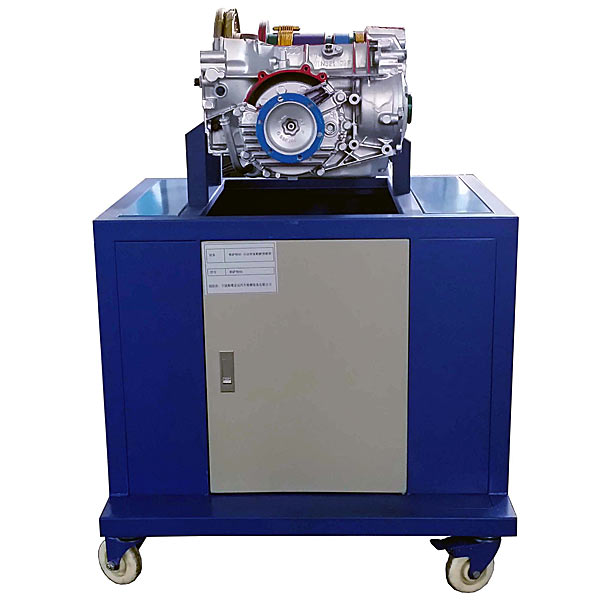
| 5 | Automatic transmission assembly | set | 1 | |
| 6 | 12V pneumatic directional valve | set | 1 | |
| 7 | Single phase gear reduction induction motor |
5IK120GN-C; 90 rpm 250W |
tower | 1 |
| 8 | Driving mechanism (with safety guard) | set | 1 | |
| 9 | gear control switch | set | 1 | |
| 10 | Mobile stand (with self-locking casters) |
1400×900×1100mm (length×width×height) cold plate stamping cabinet type with storage box |
tower | 1 |
| 11 | Air compressor and gas circuit device | tower | 1 |
 Wechat scan code follow us

24-hour hotline+86 18916464525

Phone18916464525
ADD:Factory 414, District A, No. 6, Chongnan Road, Songjiang Science and Technology Park, Shanghai ICP: Sitemap