Shanghai Daiyu Education Equipment Manufacturing Co., Ltd.
Language:


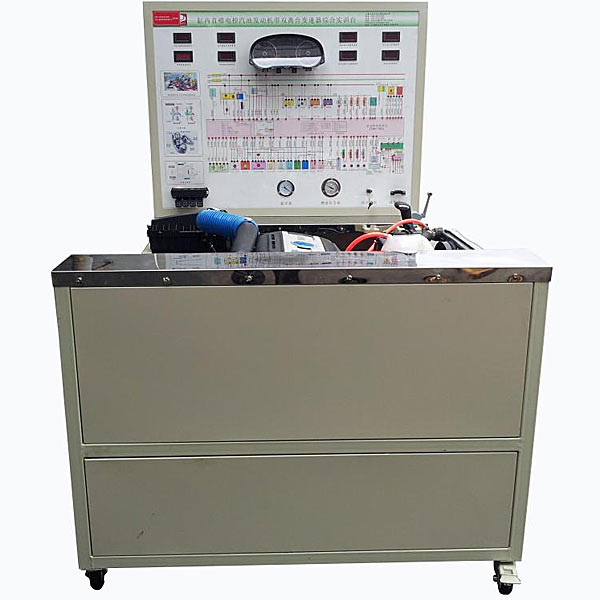


| serial number | name | Specifications and models | unit | quantity |
| 1 | Detection control panel (with panel cabinet) | Equipped with various detection terminals and color inkjet circuit diagrams | set | 1 |
| 2 | instrument cluster | Original car | set | 1 |
| 3 | Engine control computer (ECU) | Original car | tower | 1 |
| 4 | Automatic transmission control computer (ECU) | Original car | tower | 1 |
| 5 | Diagnostic seat | OBDⅡ | indivual | 1 |
| 6 | Ignition switch (with reading coil) | Original car | indivual | 1 |
| 7 | fuel pressure gauge | 0-10kg/cm2 | indivual | 1 |
| 8 | M*n oil channel pressure gauge | 0-25kg/cm2 | indivual | 1 |
| 9 | Vacuum pressure gauge | 0-76in.Hg | indivual | 1 |
| 10 | Engine assembly (with accessories) | set | 1 | |
| 11 | Automatic transmission assembly | set | 1 | |
| 12 | Transmission gear lever assembly | Original car | set | 1 |
| 13 | Fuel tank | 10L | indivual | 1 |
| 14 | Gasoline pump (including gasoline pump plug) | Original car | set | 1 |
| 15 | Throttle control | Original car | set | 1 |
| 16 | Intake and exhaust pipes (with protective cover) | Original car | set | 1 |
| 17 | brake system assembly | set | 1 | |
| 18 | Water tank (including st*nless steel protective cover) | Original car | set | 1 |
| 19 | cooling electronic fan | Original car | indivual | 2 |
| 20 | battery | 12V/65AH | tower | 1 |
| twenty one | relay | Cont*ns: starting relay, oil pump relay, cooling fan relay | set | 1 |
| twenty two | Fuse box | Route 10 | indivual | 1 |
| twenty three | m*n power switch | 50A | indivual | 1 |
| twenty four | Braking devices and accessories | Original car | set | 1 |
| 25 | Mobile stand (with self-locking casters) | 1700*1000*1700mm | tower | 1 |
| 26 | Fault simulation and troubleshooting device | set | 1 | |
| 27 | Equipment Teacher's Manual | set | 1 | |
| 28 | Equipment certificate, warranty card | set | 1 |
 Wechat scan code follow us

24-hour hotline+86 18916464525

Phone18916464525
ADD:Factory 414, District A, No. 6, Chongnan Road, Songjiang Science and Technology Park, Shanghai ICP: Sitemap