Shanghai Daiyu Education Equipment Manufacturing Co., Ltd.
Language:


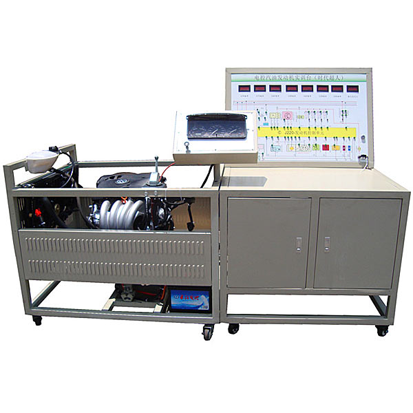


| serial number | name | Specifications and models | unit | quantity |
| 1 | Inspection control panel with panel cabinet | Equipped with various detection terminals and color circuit diagrams | set | 1 |
| 2 | Engine control computer (ECU) | Original car | set | 1 |
| 3 | Throttle control | Original car | set | 1 |
| 4 | Engine assembly (including accessories) | Original car | tower | 1 |
| 5 | Intake and exhaust pipes | Original car | set | 1 |
| 6 | Water tank, auxiliary water tank and water pipe | Original car | set | 1 |
| 7 | cooling electronic fan | 12V, 80W | indivual | 2 |
| 8 | instrument cluster | Original car | set | 1 |
| 9 | Diagnostic seat | Original car | indivual | 1 |
| 10 | Ignition switch assembly | Original car | indivual | 1 |
| 11 | fuel pressure gauge | 0-10kg/cm2 | indivual | 1 |
| 12 | Vacuum pressure gauge | 0-76in.Hg | indivual | 1 |
| 13 | St*nless steel fuel tank | 10L | indivual | 1 |
| 14 | Gasoline pump (including gasoline pump plug) | set | 1 | |
| 15 | battery | 12V 65Ah | tower | 1 |
| 11 | Wiring harness | set | 1 | |
| 12 | relay | Including: starting relay, oil pump relay, cooling fan relay, etc. | set | 1 |
| 13 | Integrated fuse and relay box | indivual | 1 | |
| 14 | m*n power switch | 50A | indivual | 1 |
| 15 | Steel mobile stand (with self-locking casters, panel cabinet and base, protective mesh panels on both sides) | 1700*1000*1300mm (length*width*height) | tower | 1 |
| 16 | Digital display for actuators and sensors | set | 1 | |
| 17 | Actuator display LED | set | 1 | |
| 18 | Air filter assembly with intake pipe | Original car | set | 1 |
| 19 | three way catalytic converter | With new muffler | set | 1 |
| 20 | Fault simulation and troubleshooting device | set | 1 | |
| twenty one | anti-theft control unit | Original car | set | 1 |
| twenty one | Equipment Teacher's Manual | set | 1 | |
| twenty two | Equipment certificate, warranty card | set | 1 |
 Wechat scan code follow us

24-hour hotline+86 18916464525

Phone18916464525
ADD:Factory 414, District A, No. 6, Chongnan Road, Songjiang Science and Technology Park, Shanghai ICP: Sitemap