Shanghai Daiyu Education Equipment Manufacturing Co., Ltd.
Language:


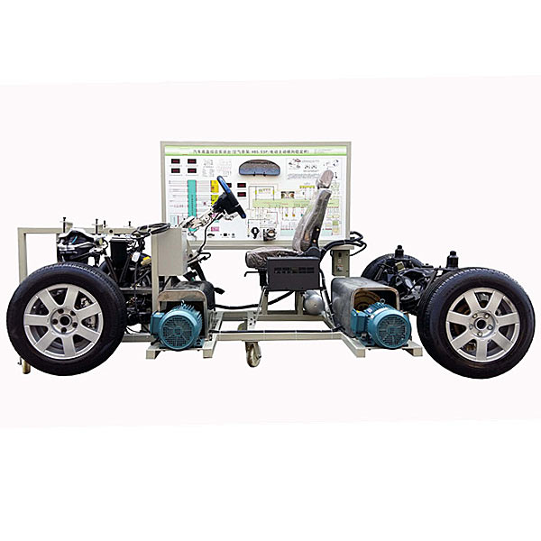


| serial number | name | Specifications and models | unit | quantity |
| 1 | Electronically controlled *r suspension system and control unit | set | 1 | |
| 2 | Steering system/steering wheel and angle sensor | set | 1 | |
| 3 | Braking System | set | 1 | |
| 4 | ABS/ESP system | set | 1 | |
| 5 | clutch interrupter | set | 4 | |
| 6 | transmission control unit | set | 1 | |
| 7 | Front and rear axles/suspension | set | 1 | |
| 8 | Shift mechanism simulator | set | 1 | |
| 9 | electric motor | Only | 2 | |
| 10 | Motor frequency converter | Only | 1 | |
| 11 | Leakage protection switches and accessories | set | 1 | |
| 12 | Driver's seat | set | 1 | |
| 13 | Steel stand with mobile casters |
Operation table: about 3000×1700×1500mm (length×width×height) Inspection table: 1740×600×1700mm (length×width×height) |
tower | 1 |
| 14 | Engine control unit and load signal device | set | 1 | |
| 15 | Engine speed regulating device | set | 1 | |
| 16 | Vehicle speed adjustment device | set | 1 | |
| 17 | instrument unit | set | 1 | |
| 18 | Switch operating unit | set | 1 | |
| 19 | Aviation wiring harness | set | 1 | |
| 20 | Inspection control panel with panel cabinet |
Equipped with various detection terminals as well as color circuit diagrams and working principle diagrams (panel: 1700*900*4mm) |
set | 1 |
| twenty one | Electronically controlled stabilizer bar device | set | 1 |
 Wechat scan code follow us

24-hour hotline+86 18916464525

Phone18916464525
ADD:Factory 414, District A, No. 6, Chongnan Road, Songjiang Science and Technology Park, Shanghai ICP: Sitemap