Shanghai Daiyu Education Equipment Manufacturing Co., Ltd.
Language:


| serial number | name | Specifications | unit | quantity |
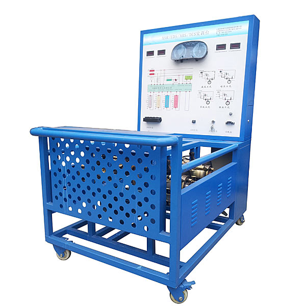
| 1 | Detection control panel (with panel cabinet) |
Equipped with various detection terminals, color circuit diagrams and hydraulic pipeline diagrams; (950*900*4mm aluminum-plastic plate, and installed with insulating bottom plate) |
set | 1 |
| 2 | ABS/ASR/ESP control unit assembly | Original car | set | 1 |
| 3 | meter | Original car | set | 1 |
| 4 | Diagnostic seat | OBDⅡ | indivual | 1 |
| 5 | Ignition Switch | indivual | 1 | |
| 6 | brake master cylinder | Original car | set | 1 |
| 7 | brake cylinder | Original car | indivual | 4 |
| 8 | brake disc | Original car | indivual | 4 |
| 9 | Brake Pads | Original car | indivual | 4 |
| 10 | outer ball cage | Original car | indivual | 4 |
| 11 | half shaft rod | Original car | strip | 4 |
| 12 | Left/right/front speed sensor | Original car | set | 1 |
| 13 | Left/right/rear speed sensors | Original car | set | 1 |
| 14 | drive belt | strip | 2 | |
| 15 | vacuum drum | Original car | set | 1 |
| 16 | brake pedal | Original car | set | 1 |
| 17 | M*n oil channel pressure gauge | 0-250kg/psi | indivual | 2 |
| 18 | brake cylinder pressure gauge | 0-100kg/psi | indivual | 4 |
| 19 | Frequency converter | tower | 2 | |
| 20 | Three-phase asynchronous motor | tower | 1 | |
| twenty one | Vacuum booster pump | set | 1 | |
| twenty two | Fault setting and assessment system | set | 1 | |
| twenty three | Mobile stand (with self-locking casters) | 1500×1000×1700mm (length×width×height) | tower | 1 |
| twenty four | Supporting equipment instruction manual | set | 1 | |
| 25 | Original service manual | Original car | set | 1 |
| 26 | steering sensor | Original car | set | 1 |
| 26 | Acceleration and deflection rate sensors | Original car | set | 1 |
| 27 | Gateway communication related components | Original car | set | 1 |
 Wechat scan code follow us

24-hour hotline+86 18916464525

Phone18916464525
ADD:Factory 414, District A, No. 6, Chongnan Road, Songjiang Science and Technology Park, Shanghai ICP: Sitemap