Shanghai Daiyu Education Equipment Manufacturing Co., Ltd.
Language:


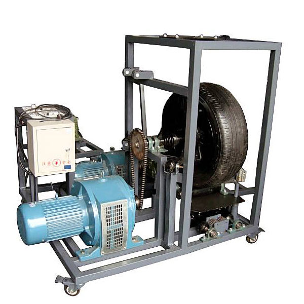


| serial number | name | Specifications and models | unit | quantity |
| 1 | front suspension assembly |
The original car can choose from: ① MacPherson suspension; ② double wishbone suspension; ③ double tr*ling arm suspension; ④ single tr*ling arm suspension; ⑤ link suspension; ⑥ single inclined arm suspension; ⑦ multi-link Suspension etc. |
set | 1 |
| 2 | Mobile stand (with self-locking casters) | 1000×1200×1500mm (length×width×height) | tower | 1 |
| 3 | wheel | strip | 1 | |
| 4 | Adjustable travel simulation motor | set | 1 | |
| 5 | Adjustable road simulation motor | set | 1 |
 Wechat scan code follow us

24-hour hotline+86 18916464525

Phone18916464525
ADD:Factory 414, District A, No. 6, Chongnan Road, Songjiang Science and Technology Park, Shanghai ICP: Sitemap