Shanghai Daiyu Education Equipment Manufacturing Co., Ltd.
Language:


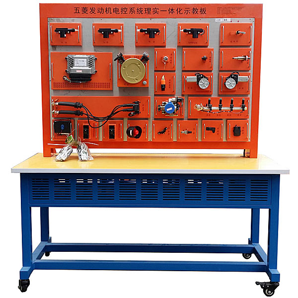


This equipment uses real components of the automotive sensor and actuator system to fully demonstrate the structure and working process of the automotive sensor and actuator system.
It is suitable for the teaching needs of schools on the theory and m*ntenance tr*ning of automobile sensor and actuator systems.
two. Functional features
1. Use complete engine sensor and actuator components (components are made of building block modules, flexible placement and fixation of experimental pendants), and use the crankshaft sensor signal wheel to simulate engine operation; after the experimental plug-in wires are connected, the actual Demonstrate the working process of engine sensors, control units, and actuators (such as spark plug ignition, fuel injector injection, and fuel pump working processes.)
2. Install the original vehicle engine control unit, instrument cluster, fuel tank, oil pump, and oil pump relay , fuse box, 4 fuel injectors, fuel injection pipe, fuel injection measuring cup, movable stand, multiple sensors and actuators.
3. There is a color printed circuit diagram on the teaching board panel. Students can visually connect the sensors and actuators by comparing the circuit diagram, and understand and analyze the working principle of the automotive sensor and actuator system.
4. The teaching board is equipped with a fuel tank, fuel quantity sensor, engine control unit, instrument cluster, oil pump relay, ignition switch, diagnostic socket, fuse box, injector and measuring cup, and detection terminals are installed on the panel, which can be directly Detect electrical signals from the engine control system circuit components on the panel.
5. There is a detection terminal installed on the sensor side of the equipment panel, which can directly connect the sensor and actuator.
6. Simulate the crankshaft position sensor signal to make the fuel pump work, the injector sprays fuel, and the spark plug ignites.
7. The equipment is equipped with a diagnostic socket, which can be connected to a dedicated or universal car decoder to query the ECU code of the engine control unit, read fault codes, clear fault codes, read data streams, test actuators, and set parameters. Waveform analysis and other self-diagnostic functions.
8. The equipment panel part adopts 1.5mm cold plate stamping structure, with beautiful appearance; the bottom part adopts steel structure welding, the surface is spray-coated, with self-locking caster device, and the base of the teaching board is equipped with a tabletop of about 40cm, which is convenient Place information, light testing instruments, etc.
9. The bottom frame of the equipment is welded with a steel structure, the surface is p*nted, and equipped with self-locking casters for flexible movement.
10. The equipment works with ordinary 220V AC power supply, which is transformed into 12V DC power supply through internal circuit transformation and rectification. No battery is needed, which reduces the trouble of charging. The 12V DC power supply has the function of preventing short circuit.
11. The components are made of building block modules, and the fixing parts are stamped and formed by cold plates.
12. The experimental table is made of steel and wood structure, which is beautiful and elegant.
13. Mechanical assembly and fitter assembly virtual simulation software: This software is developed based on unity3d, with optional 6-level image quality. It is equipped with the design and virtual disassembly and assembly of reducers and shafting structures, the design and simulation of common mechanical mechanisms , and a mechanism resource library. For a typical mechanical mechanism (virtual disassembly and assembly of a gasoline engine), the software is a whole software and cannot be individual resources.
A. Reducer design and virtual disassembly interface can choose worm gear bevel gear reducer, two-stage expanded cylindrical gear reducer, bevel cylindrical gear reducer, coaxial cylindrical gear reducer, bevel gear reducer, and one-stage cylindrical gear reducer. Gear reducer.
Worm bevel gear reducer: After entering the software, the assembly content is automatically played. Each step in the video has a text description
. Secondary expandable cylindrical gear reducer: After entering the software, the content is played in the form of a video. The video content should include: Part name ( Scan the QR code to see the names of parts), disassembly and assembly demonstration (including disassembly and assembly), virtual disassembly (including overall, low-speed shaft, medium-speed shaft, high-speed shaft, box cover, box seat)
conical cylindrical gear reducer, Coaxial cylindrical gear reducer, bevel gear reducer, first-level cylindrical gear reducer: click to enter and automatically jump to the edrawings interface. The models are all three-dimensional models. By clicking on the parts, the names of the parts are displayed, and the 360° view is av*lable Rotate, enlarge, reduce, translate, and at the same time, the entire reducer can be disassembled and assembled through the moving parts function. At the same time, you can select the home button to return to the original state of the reducer. The bevel gear reducer and the first-stage cylindrical gear reducer have added the function of inserting a cross section, and the cross section can be freely dragged to observe the internal structure of the reducer.
B. Shaft structure design and virtual disassembly and assembly interface optional parts recognition, disassembly and assembly demonstration, and actual operation.
1. Parts recognition: three-dimensional model and part name including helical gear, non-hole end cover, coupling, coupling key, shaft, gear key, hole end cover, shaft sleeve, deep groove ball bearing, any All parts can be rotated 360°
2. Disassembly and assembly demonstration: There are 2 built-in cases. When you move the mouse to the position of a cert*n part (except the base and bearing seat), the part will automatically enlarge and the name of the part will be displayed. It is equipped with disassembly and Assembly button, the function is to automatically complete the disassembly and assembly of the shaft system structure by the software. All three-dimensional scenes can be rotated, enlarged, reduced and translated 360° in all directions.
3. Practical operation: The three-dimensional parts are neatly placed on the table. The students manually select the corresponding parts and move them to the shaft system structure. The parts can be installed only when they are placed in the correct order and in the correct position. There is a restart button to facilitate students to restart. Conduct virtual experiments. When you move the mouse to a cert*n part position (except the base and bearing seat), the part will automatically enlarge and the part name will be displayed.
C. Common mechanical mechanism design and simulation, optional hinge four-bar mechanism design and analysis, I\II type crank rocker mechanism design and analysis, offset crank slider mechanism design and analysis, crank swing guide rod mechanism design and analysis, hinge Four-bar mechanism with integrated trajectory, eccentric linear-acting roller push rod cam , and centering linear-acting flat-bottomed push rod cam.
1. Each mechanism should be able to input corresponding parameters, and the software can automatically calculate the parameters, and can perform motion simulation and automatically draw curves.
D. The mechanism resource library includes 11 types of planar link mechanisms, 5 types of cam mechanisms, 6 types of gear mechanisms, 8 types of transmission mechanisms, 11 types of tightening mechanisms, 6 types of gear tr*n mechanisms, and 8 types of other mechanisms (mechanical equipment simulation)
E , Virtual disassembly and assembly of gasoline engines, optional crankcase assembly and disassembly demonstration, crankcase virtual assembly, valve tr*n assembly and disassembly demonstration, valve tr*n virtual assembly
1. Both the crankcase assembly and disassembly demonstration and the gas distribution system assembly and disassembly demonstration are equipped with disassembly buttons, assembly buttons, restart, and disassembly observation buttons. When the mouse is moved to a cert*n part position, the part will automatically enlarge and the part name will be displayed. , the function is to automatically complete the disassembly and assembly of the shaft system structure by the software. When using the decomposition observation button, the 3D model of the crankcase or gas distribution system automatically displays an exploded view, which can be rotated, enlarged, reduced, and translated 360°.
2. The 3D parts of the crankcase virtual assembly and the gas distribution system virtual assembly are neatly arranged When placed on the desktop, students manually select the corresponding parts and move them to the mechanism. The parts can be installed only when they are placed in the correct order and in the correct position. There is a restart button to facilitate students to re-perform the virtual experiment. When you move the mouse to cert*n part locations, the part names are automatically displayed.
3. Technical specifications
Overall dimensions (approx.): 1600×600×1700mm (length×width×height)
External power supply: AC 220V±10% 50Hz
working voltage: DC 12V
working temperature: -40℃~+50℃
Fuel pressure gauge: 0~10kg/psi
Color: 7032
Steel pipe: 40*40*3mm
Cabinet: 1.5mm cold plate stamping forming, m*ntenance door set on the back;
Mobile casters: 100*60mm
IV. Basic configuration (each unit)
| serial number | name | Specifications and models | unit | quantity |
| 1 | Test control panel | Equipped with various detection terminals as well as color circuit diagrams and working principle diagrams | set | 1 |
| 2 | Signal simulation device | set | 1 | |
| 3 | Diagnostic seat | indivual | 1 | |
| 4 | Ignition Switch | brand new | indivual | 1 |
| 5 | Distributorless ignition system | Cont*ns engine control computer (ECU), crankshaft position sensor, igniter assembly, spark plug, etc. | set | 1 |
| 6 | Fuel tank | 10L | indivual | 1 |
| 7 | Gasoline pump (including gasoline pump plug) | brand new | set | 1 |
| 8 | oil pump relay | indivual | 1 | |
| 9 | fuel injector | Comes with 4 120ml glass measuring cups | set | 1 |
| 10 | fuel injector | brand new | indivual | 4 |
| 11 | fuel pressure gauge | 0~10kg/psi | indivual | 1 |
| 12 | Crankshaft position sensor and signal wheel | set | 1 | |
| 13 | Throttle body assembly | set | 1 | |
| 14 | Engine sensors and actuators (complete set) | set | 1 | |
| 15 | Mobile stand (with self-locking casters) | 1600×600×1700mm (length×width×height) | tower | 1 |
| 16 | Experimental plug wire | set | 1 | |
| 17 | Building block module | Cold plate stamping forming | set | 1 |
 Wechat scan code follow us

24-hour hotline+86 18916464525

Phone18916464525
ADD:Factory 414, District A, No. 6, Chongnan Road, Songjiang Science and Technology Park, Shanghai ICP: Sitemap