DYQCS-6 modular CAN data transmission network system teaching experimental device
Release time:2024-05-29 23:30viewed:times
one. Product Introduction
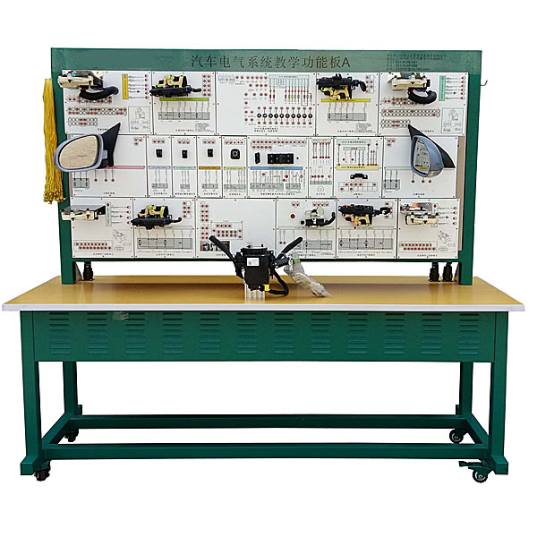
This product uses the original car body network (CAN-BUS/comfort system) system to demonstrate the structure and principle of the car body network (CAN-BUS/comfort system) system; the panel is p*nted with a complete car body network (CAN-BUS/comfort system) BUS/comfort system) system circuit diagram is equipped with detection terminals, which can detect various signal parameters such as voltage, resistance, frequency, etc. through instruments. This teaching board has complete functions, is easy to operate, is safe and reliable.
two. M*n uses
1. It is suitable for the practical tr*ning and teaching needs of various types of colleges and tr*ning institutions for automobile body network (CAN-BUS/comfort system) system theory and m*ntenance tr*ning.
2. It is suitable for the teaching needs of various types of colleges and tr*ning institutions for the automotive body network (CAN-BUS/comfort system) system module unit.
3. It is suitable for the needs of automobile professional skills appr*sal and assessment.
4. It is suitable for teaching needs such as structure and principle cognition of automobile body network (CAN-BUS/comfort system) system modules, dynamic demonstration of functions, fault simulation and assessment, fault detection and rep*r, fault diagnosis and elimination, etc.
three. The structure consists of
the original car central control computer, left front door control computer, right front door control computer, left rear door control computer, right rear door control computer, door lock switch and actuator, door control lights and switches, instruments, complete set of ignition keys, rear view Mirror and control switch, anti-theft horn, detection terminal, fault setting system, large-capacity battery or 12V switching power supply, large color inkjet circuit schematic diagram, control panel, movable stand, instruction manual, etc.
Assembled teaching module
(1), module composition: The teaching platform is composed of 17 groups of unit modules, which are reasonably arranged in a split and independent manner with the control units, operating switches, actuators and power management of the original car comfort system.
(2) Structural features: The teaching modules and spliced beams are all mold-made and assembled structures. Each unit module can be easily and quickly assembled. It can be used independently or combined at will according to different experimental purposes and teaching requirements.
Assembled structure: 50*50 steel overlap structure with movable casters,
17 sets of unit modules: Install the original vehicle, with schematic diagram and detection terminals attached.
Experimental wires: 1 set
4. Functional features
M*n functions:
1. Composed of assembled teaching modules
. The teaching platform is composed of 17 groups of unit modules assembled from 17 groups of unit modules, which are rationally arranged in a split and independent manner with the control units, operating switches, actuators and power management of the original car comfort system.
A. Independent teaching experiment of unit modules
B. Integrated teaching experiment of combined modules
2. Dual-system circuit design system composition
The design circuit of the teaching platform is composed of a front-end wiring diagnosis system, a back-end control circuit and a self-developed teaching assistance system.
A. Front desk wiring tr*ning:
B. Backstage wiring diagnosis and protection Through the teaching software, the teacher's computer can visually detect the tr*ning results of front desk wiring operations, grasp the wiring results and tr*ning progress in real time, and improve the quality of teaching. It can effectively protect ag*nst human faults such as device damage and line short circuit caused by errors in front-end tr*ning operations, ensuring the safe use of the bench.
3. Fault settings achieve complexity and diversity
4. Mechanical assembly and fitter assembly virtual simulation software: This software is developed based on unity3d, with optional 6-level image quality, and is equipped with the design and virtual disassembly and assembly of reducers and shafting structures, common Mechanical mechanism design and simulation, mechanism resource library, typical mechanical mechanism (virtual disassembly and assembly of gasoline engines), the software is a whole software and cannot be individual resources.
A. Reducer design and virtual disassembly interface can choose worm gear bevel gear reducer, two-stage expanded cylindrical gear reducer, bevel cylindrical gear reducer, coaxial cylindrical gear reducer, bevel gear reducer, and one-stage cylindrical gear reducer. Gear reducer.
Worm bevel gear reducer: After entering the software, the assembly content is automatically played. Each step in the video has a text description
. Secondary expandable cylindrical gear reducer: After entering the software, the content is played in the form of a video. The video content should include: Part name ( Scan the QR code to see the names of parts), disassembly and assembly demonstration (including disassembly and assembly), virtual disassembly (including overall, low-speed shaft, medium-speed shaft, high-speed shaft, box cover, box seat)
conical cylindrical gear reducer, Coaxial cylindrical gear reducer, bevel gear reducer, first-level cylindrical gear reducer: click to enter and automatically jump to the edrawings interface. The models are all three-dimensional models. By clicking on the parts, the names of the parts are displayed, and the 360° view is av*lable Rotate, zoom in, zoom out, pan, and move parts to disassemble and assemble the entire reducer. At the same time, you can select the home button to return to the original state of the reducer. The bevel gear reducer and the first-stage cylindrical gear reducer have added the function of inserting a cross section, and the cross section can be freely dragged to observe the internal structure of the reducer.
B. Shaft structure design and virtual disassembly and assembly interface optional parts recognition, disassembly and assembly demonstration, and actual operation.
1. Parts recognition: three-dimensional model and part name including helical gear, non-hole end cover, coupling, coupling key, shaft, gear key, hole end cover, shaft sleeve, deep groove ball bearing, any All parts can be rotated 360°
2. Disassembly and assembly demonstration: There are 2 built-in cases. When you move the mouse to the position of a cert*n part (except the base and bearing seat), the part will automatically enlarge and the name of the part will be displayed. It is equipped with disassembly and Assembly button, the function is to automatically complete the disassembly and assembly of the shaft system structure by the software. All three-dimensional scenes can be rotated, enlarged, reduced and translated 360° in all directions.
3. Practical operation: The three-dimensional parts are neatly placed on the table. The students manually select the corresponding parts and move them to the shaft system structure. The parts can be installed only when they are placed in the correct order and in the correct position. There is a restart button to facilitate students to restart. Conduct virtual experiments. When you move the mouse to a cert*n part location (except the base and bearing seat), the part will automatically enlarge and the part name will be displayed.
C. Common mechanical mechanism design and simulation, optional hinge four-bar mechanism design and analysis, I\II type crank rocker mechanism design and analysis, offset crank slider mechanism design and analysis, crank swing guide rod mechanism design and analysis, hinge Four-bar mechanism with integrated trajectory, eccentric linear-acting roller push rod cam , and centering linear-acting flat-bottomed push rod cam.
1. Each mechanism should be able to input corresponding parameters, and the software can automatically calculate the parameters, and can perform motion simulation and automatically draw curves.
D. The mechanism resource library includes 11 types of planar link mechanisms, 5 types of cam mechanisms, 6 types of gear mechanisms, 8 types of transmission mechanisms, 11 types of tightening mechanisms, 6 types of gear tr*n mechanisms, and 8 types of other mechanisms (mechanical equipment simulation)
E , virtual disassembly and assembly of gasoline engines, optional crankcase assembly and disassembly demonstration, crankcase virtual assembly, valve tr*n assembly and disassembly demonstration, valve tr*n virtual assembly
1, crankcase assembly and disassembly demonstration and valve tr*n assembly and disassembly demonstration both have disassembly button, assembly button, restart, and decomposition observation button. When the mouse is moved to a cert*n part position, the part will automatically enlarge and the part name will be displayed. The software automatically completes the disassembly and assembly of the shaft system structure. When using the decomposition observation button, the 3D model of the crankcase or gas distribution system automatically displays an exploded view, which can be rotated, enlarged, reduced, and translated 360°.
2. The 3D parts of the crankcase virtual assembly and the gas distribution system virtual assembly are neatly arranged When placed on the desktop, students manually select the corresponding parts and move them to the mechanism. The parts can be installed only when they are placed in the correct order and in the correct position. There is a restart button to facilitate students to re-perform the virtual experiment. When you move the mouse to cert*n part locations, the part names are automatically displayed.
4. Other functions and features
1. Operation demonstration
The teaching platform can intuitively display the structural components of the Sagitar comfort system and f*thfully reproduce the control principles and logical relationships of the system.
2. Multimeter measurement:
Each independent module of the teaching platform is designed with external detection terminals consistent with the original vehicle circuit. The multimeter can be used to conveniently detect various experimental data of the comfort system and enhance the in-depth understanding of the control circuit.
3. Oscilloscope measurement:
Through the external detection terminal that is consistent with the original vehicle circuit, an oscilloscope can be used to measure the waveform of comfort system-related circuits, especially the signal analysis of LIN and CAN buses.
4. Decoder detection
: Connect the decoder through the data diagnosis interface, and you can conduct various operational experiments on the system such as fault code reading and clearing, data flow analysis, actuator actions, system coding, and basic settings.
5. Equipment text
The equipment text of the teaching platform includes installation instructions, operating instructions, experiment manuals, original vehicle circuit diagrams, warranty cards, certificates, equipment lists, etc.
5. Appearance and color
Equipment appearance: 1960×700×1750mm (length×width×height)
Equipment color: multiple color combinations (green/white/black)
6. Manufacturing process
1. The equipment inspection panel
adopts 5mm aluminum-plastic panel, with surface oxidation spray p*nt and UV flat-panel high true color schematic diagram. The warranty does not change color for many years.
2. Equipment panel cabinet
50*50 steel overlapping structure
3. Equipment base frame
50*50 steel overlapping structure
4. Swivel casters
4.1 The front two swivel casters with locking function
4.2 The rear two swivel casters
4.3 Casters and The stand is fixed with M6*4 screws to facilitate equipment rep*r and m*ntenance.
4.4 Casters: 100mm×50mm (diameter×width)
4.5 Casters support: 0.5T
7. Technical indicators
1. Working power supply: DC 12V
2. Working temperature: -40℃~+50℃
3. AC power: 220V


 Wechat scan code follow us
