Shanghai Daiyu Education Equipment Manufacturing Co., Ltd.
Language:


| serial number | name | Specifications and models | unit | quantity |
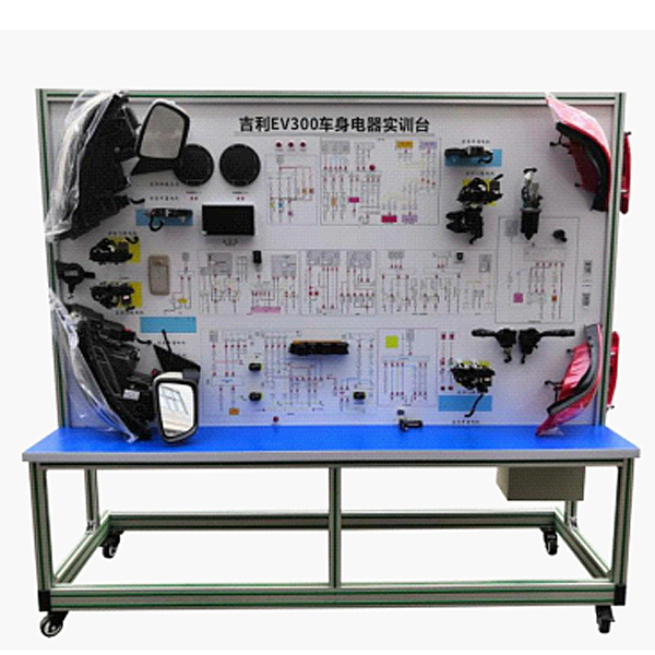
| 1 | Teaching pendant panel | Equipped with various detection terminals and color circuit diagrams | set | 1 |
| 2 | Ignition Switch | Original car | indivual | 1 |
| 3 | instrument cluster | Original car | set | 1 |
| 4 | Combination Switch | Original car | set | 1 |
| 5 | Left and right headlight assemblies | Original car | set | 1 |
| 6 | Left and right front fog lights | Original car | set | 1 |
| 7 | Left and right turn signals | Original car | set | 1 |
| 8 | Left and right turn side lights | Original car | set | 1 |
| 9 | Left and right combination t*l lights | Original car | set | 1 |
| 10 | License Plate Light | Original car | set | 1 |
| 11 | DC power conversion system | Original car | set | 1 |
| 12 | light switch | Original car | set | 1 |
| 13 | brake light switch | Original car | set | 1 |
| 14 | Reversing light switch | Original car | set | 1 |
| 15 | hazard light switch | Original car | set | 1 |
| 16 | Wiring harness | Supporting | set | 1 |
| 17 | Wiper assembly | Original car | set | 1 |
| 18 | wiper controller | Original car | indivual | 1 |
| 19 | Water jet motor | Original car | set | 1 |
| 20 | watering bottle | Original car | set | 1 |
| twenty one | trumpet | Original car | indivual | 2 |
| twenty two | Horn relay | Original car | indivual | 1 |
| twenty three | Various types of relays | Original car | set | 1 |
| twenty four | fog lights | Original car | indivual | 1 |
| 25 | Electric windows and central control switch | Original car | set | 1 |
| 26 | Electric mirrors and switches | Original car | set | 1 |
| 27 | central locking computer | Original car | indivual | 1 |
| 28 | door lock motor | Original car | set | 1 |
| 29 | power window motor | Original car | set | 1 |
| 30 | Audio assembly | Original car | set | 1 |
| 31 | speaker | 6", 200W | right | 1 |
| 32 | Auxiliary battery | 12V 45Ah | tower | 1 |
| 33 | Fuse box | Supporting | indivual | 2 |
| 34 | m*n power switch | 50A | indivual | 1 |
| 35 | Mobile stand (with self-locking casters) | 1740×650×1700mm (length×width×height) | tower | 1 |
| 36 | Fault simulation and troubleshooting device | Supporting | set | 1 |
| 37 | Teacher's Manual | Supporting | set | 1 |
| 38 | Certificate and warranty card | Supporting | set | 1 |
 Wechat scan code follow us

24-hour hotline+86 18916464525

Phone18916464525
ADD:Factory 414, District A, No. 6, Chongnan Road, Songjiang Science and Technology Park, Shanghai ICP: Sitemap