DYXNYDP-04 Electric Vehicle Electric Vacuum System Experimental Device
Release time:2024-05-27 13:00viewed:times
Product Introduction:
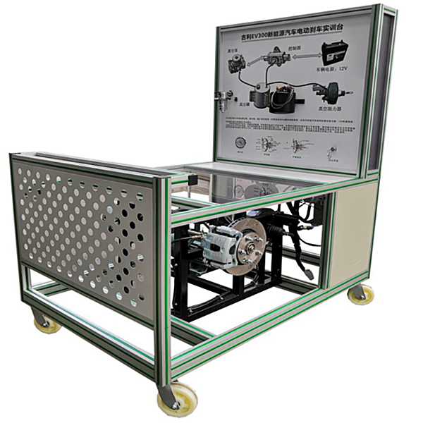
M*nstream new energy electric vacuum-assisted hydraulic brake components are selected. The functions and control methods are exactly the same as those of general pure electric vehicles. It truly shows the connection control relationship and installation position between new energy electric vacuum-assisted hydraulic brake components. and operating parameters, and the vacuum degree is displayed through the vacuum gauge, so that students can understand the principle of triggering the vacuum pump by vacuum degree, and cultivate their ability to analyze and deal with electric vacuum booster faults.
Functional features
1. Real and operable new energy electric vacuum-assisted hydraulic braking, fully demonstrating the composition structure and logical control relationship of each m*n component.
2. Each m*n component is installed on the bench, and the electrical connection method is the same as that of the actual vehicle, which can be easily disassembled, allowing students to master the key points of disassembly and assembly of electric vacuum-assisted hydraulic brake components during the disassembly and assembly process;
3. Vacuum gauge and vacuum The tank is connected and installed on the bench panel. The panel displays the current closing and disconnection of the vacuum pump at the same time. Press the brake pedal and observe the control relationship between the height of the vacuum gauge and the starting and running status of the vacuum pump. When the vacuum drops to -45Kpa, the pressure sensor Turn on the 12V power supply and the vacuum pump will work; when the vacuum degree rises to -80Kpa, the pressure sensor will disconnect the 12V power supply and the vacuum pump will stop working; through actual observation, students will master the working principle of pure electric vacuum assist.
4. The tr*ning platform is placed horizontally and the m*n components are installed; 4 casters are installed at the bottom of the platform for flexible movement. It is equipped with a self-locking caster device to fix the position.
5. Equipped with safety protection devices such as brake shields.
6. Equipped with an anatomically complete vacuum pump assembly, vacuum tank assembly, and booster belt pump assembly, showing the structure of the m*n components of the electric vacuum booster system.
7. Mechanical assembly and fitter assembly virtual simulation software: This software is developed based on unity3d, with optional 6-level image quality. It is equipped with the design and virtual disassembly and assembly of reducers and shafting structures, the design and simulation of common mechanical mechanisms , and a mechanism resource library. For a typical mechanical mechanism (virtual disassembly and assembly of a gasoline engine), the software is a whole software and cannot be individual resources.
A. Reducer design and virtual disassembly interface can choose worm gear bevel gear reducer, two-stage expanded cylindrical gear reducer, bevel cylindrical gear reducer, coaxial cylindrical gear reducer, bevel gear reducer, and one-stage cylindrical gear reducer. Gear reducer.
Worm bevel gear reducer: After entering the software, the assembly content is automatically played. Each step in the video has a text description
. Secondary expandable cylindrical gear reducer: After entering the software, the content is played in the form of a video. The video content should include: Part name ( Scan the QR code to see the names of parts), disassembly and assembly demonstration (including disassembly and assembly), virtual disassembly (including overall, low-speed shaft, medium-speed shaft, high-speed shaft, box cover, box seat)
conical cylindrical gear reducer, Coaxial cylindrical gear reducer, bevel gear reducer, first-level cylindrical gear reducer: click to enter and automatically jump to the edrawings interface. The models are all three-dimensional models. By clicking on the parts, the names of the parts are displayed, and the 360° view is av*lable Rotate, zoom in, zoom out, pan, and move parts to disassemble and assemble the entire reducer. At the same time, you can select the home button to return to the original state of the reducer. The bevel gear reducer and the first-stage cylindrical gear reducer have added the function of inserting a cross section, and the cross section can be freely dragged to observe the internal structure of the reducer.
B. Shaft structure design and virtual disassembly and assembly interface optional parts recognition, disassembly and assembly demonstration, and actual operation.
1. Parts recognition: three-dimensional model and part name including helical gear, non-hole end cover, coupling, coupling key, shaft, gear key, hole end cover, shaft sleeve, deep groove ball bearing, any All parts can be rotated 360°
2. Disassembly and assembly demonstration: There are 2 built-in cases. When you move the mouse to the position of a cert*n part (except the base and bearing seat), the part will automatically enlarge and the name of the part will be displayed. It is equipped with disassembly and Assembly button, the function is to automatically complete the disassembly and assembly of the shaft system structure by the software. All three-dimensional scenes can be rotated, enlarged, reduced and translated 360° in all directions.
3. Practical operation: The three-dimensional parts are neatly placed on the table. Students manually select the corresponding parts and move them to the shaft system structure. The parts can be installed only when they are placed in the correct order and in the correct position. There is a restart button to facilitate students to restart. Conduct virtual experiments. When you move the mouse to a cert*n part position (except the base and bearing seat), the part will automatically enlarge and the part name will be displayed.
C. Common mechanical mechanism design and simulation, optional hinge four-bar mechanism design and analysis, I\II type crank rocker mechanism design and analysis, offset crank slider mechanism design and analysis, crank swing guide rod mechanism design and analysis, hinge Four-bar mechanism with integrated trajectory, eccentric linear-acting roller push rod cam , and centering linear-acting flat-bottomed push rod cam .
1. Each mechanism should be able to input corresponding parameters, and the software can automatically calculate the parameters, and can perform motion simulation and automatically draw curves.
D. The mechanism resource library includes 11 types of planar link mechanisms, 5 types of cam mechanisms, 6 types of gear mechanisms, 8 types of transmission mechanisms, 11 types of tightening mechanisms, 6 types of gear tr*n mechanisms, and 8 types of other mechanisms (mechanical equipment simulation)
E , virtual disassembly and assembly of gasoline engines, optional crankcase assembly and disassembly demonstration, crankcase virtual assembly, valve tr*n assembly and disassembly demonstration, valve tr*n virtual assembly
1. Crankcase assembly and disassembly demonstration and valve tr*n assembly and disassembly demonstration both have disassembly button, assembly button, restart, and decomposition observation button. When the mouse is moved to a cert*n part position, the part will automatically enlarge and the part name will be displayed. The software automatically completes the disassembly and assembly of the shaft system structure. When using the decomposition observation button, the 3D model of the crankcase or gas distribution system automatically displays an exploded view, which can be rotated, enlarged, reduced, and translated 360°.
2. The 3D parts of the crankcase virtual assembly and the gas distribution system virtual assembly are neatly arranged When placed on the desktop, students manually select the corresponding parts and move them to the mechanism. The parts can be installed only when they are placed in the correct order and in the correct position. There is a restart button to facilitate students to re-perform the virtual experiment. When you move the mouse to cert*n part locations, the part names are automatically displayed.
Technical specifications
1. Overall dimensions (mm): 1500*1000*1700 (length*width*height)
2. Input power supply: AC220V±10% 50Hz
3. Switching power supply: AC220V-DC12V-30A
4. Working temperature: -20°~+40°
Practical tr*ning project
1. Principle of new energy electric vacuum assist control, understanding of the changing rules of vacuum degree during vehicle
braking. 2. Understand the functions of the m*n components of the new energy electric vacuum booster.
3. Understanding the role of the pressure sensing module in logic control and its relationship with the degree of vacuum.
4. New energy electric vacuum assist fault analysis and diagnosis.
Basic configuration:
drive shaft, front wheel disc brake, booster with pump assembly, vacuum pump assembly, vacuum tank assembly, switching power supply, DC motor , vacuum gauge, mobile bench; vacuum pump assembly (anatomy), vacuum tank assembly (anatomy), booster belt pump assembly (anatomy).


 Wechat scan code follow us
