DYXNYQD-13 New Energy Vehicle Electric Performance Experimental Device
Release time:2024-05-25 23:30viewed:times
1. Equipment overview
1. Overview
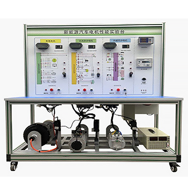
The new energy motor performance test bench consists of a tr*ning bench , a DC power supply, three common motors for new energy vehicles (permanent magnet synchronous, AC asynchronous, and hub motor), and three supporting motor controllers for new energy vehicles. , accelerator pedal, gear shifter, digital display voltage and ammeter, tachometer, torque meter, power meter and other modules.
2. Functional features:
1. The equipment can simulate the state of the motor of an electric vehicle at constant speed, acceleration, deceleration, uphill and downhill conditions, and the operation is consistent with that of a real electric vehicle.
2. The tr*ning platform can display dynamic parameters during motor rotation, such as voltage, current, torque, speed, power, etc.
3. The motor test host computer software can display the change curves of motor torque, speed, and power over a period of time, and can visually display the changes of these parameters during the motor acceleration and deceleration process.
4. The equipment is equipped with a fault assessment device, which can set faults on the lines and tr*n students' ability to troubleshoot line faults. At the same time, teachers can use the equipment to assess students' abilities.
5. Tr*n students’ abilities in motor disassembly, measurement, and structural cognition. At the same time, teachers can use equipment to assess students’ abilities.
6. Mechanical assembly and fitter assembly virtual simulation software: This software is developed based on unity3d, with optional 6-level image quality. It is equipped with the design and virtual disassembly and assembly of reducers and shafting structures, the design and simulation of common mechanical mechanisms , and a mechanism resource library. For a typical mechanical mechanism (virtual disassembly and assembly of a gasoline engine), the software is a whole software and cannot be individual resources.
A. Reducer design and virtual disassembly interface can choose worm gear bevel gear reducer, two-stage expanded cylindrical gear reducer, bevel cylindrical gear reducer, coaxial cylindrical gear reducer, bevel gear reducer, and one-stage cylindrical gear reducer. Gear reducer.
Worm bevel gear reducer: After entering the software, the assembly content is automatically played. Each step in the video has a text description
. Secondary expandable cylindrical gear reducer: After entering the software, the content is played in the form of a video. The video content should include: Part name ( Scan the QR code to see the names of parts), disassembly and assembly demonstration (including disassembly and assembly), virtual disassembly (including overall, low-speed shaft, medium-speed shaft, high-speed shaft, box cover, box seat)
conical cylindrical gear reducer, Coaxial cylindrical gear reducer, bevel gear reducer, first-level cylindrical gear reducer: click to enter and automatically jump to the edrawings interface. The models are all three-dimensional models . By clicking on the parts, the names of the parts are displayed, and the 360° view is av*lable Rotate, enlarge, reduce, translate, and at the same time, the entire reducer can be disassembled and assembled through the moving parts function. At the same time, you can select the home button to return to the original state of the reducer. The bevel gear reducer and first-stage cylindrical gear reducer have added the function of inserting a cross section, and the cross section can be freely dragged to observe the internal structure of the reducer.
B. Shaft structure design and virtual disassembly and assembly interface optional parts recognition, disassembly and assembly demonstration, and actual operation.
1. Parts recognition: three-dimensional model and part name including helical gear, non-hole end cover, coupling, coupling key, shaft, gear key, hole end cover, shaft sleeve, deep groove ball bearing, any All parts can be rotated 360°
2. Disassembly and assembly demonstration: There are 2 built-in cases. When you move the mouse to the position of a cert*n part (except the base and bearing seat), the part will automatically enlarge and the name of the part will be displayed. It is equipped with disassembly and Assembly button, the function is to automatically complete the disassembly and assembly of the shaft system structure by the software. All three-dimensional scenes can be rotated, enlarged, reduced and translated 360° in all directions.
3. Practical operation: The three-dimensional parts are neatly placed on the table. Students manually select the corresponding parts and move them to the shaft system structure. The parts can be installed only when they are placed in the correct order and in the correct position. There is a restart button to facilitate students to restart. Conduct virtual experiments. When you move the mouse to a cert*n part position (except the base and bearing seat), the part will automatically enlarge and the part name will be displayed.
C. Common mechanical mechanism design and simulation, optional hinge four-bar mechanism design and analysis, I\II type crank rocker mechanism design and analysis, offset crank slider mechanism design and analysis, crank swing guide rod mechanism design and analysis, hinge Four-bar mechanism with integrated trajectory, eccentric linear-acting roller push rod cam , and centering linear-acting flat-bottomed push rod cam .
1. Each mechanism should be able to input corresponding parameters, and the software can automatically calculate the parameters, and can perform motion simulation and automatically draw curves.
D. The mechanism resource library includes 11 types of planar link mechanisms, 5 types of cam mechanisms, 6 types of gear mechanisms, 8 types of transmission mechanisms, 11 types of tightening mechanisms, 6 types of gear tr*n mechanisms, and 8 types of other mechanisms (mechanical equipment simulation)
E , virtual disassembly and assembly of gasoline engines, optional crankcase assembly and disassembly demonstration, crankcase virtual assembly, valve tr*n assembly and disassembly demonstration, valve tr*n virtual assembly
1, crankcase assembly and disassembly demonstration and valve tr*n assembly and disassembly demonstration both have disassembly button, assembly button, restart, and decomposition observation button. When the mouse is moved to a cert*n part position, the part will automatically enlarge and the part name will be displayed. The software automatically completes the disassembly and assembly of the shaft system structure. When the decomposition observation button is used, the 3D model of the crankcase or gas distribution system automatically displays an exploded view, which can be rotated, enlarged, reduced, and translated 360°.
2. The 3D parts of the crankcase virtual assembly and the gas distribution system virtual assembly are neatly arranged When placed on the desktop, students manually select the corresponding parts and move them to the mechanism. The parts can be installed only when they are placed in the correct order and in the correct position. There is a restart button to facilitate students to re-perform the virtual experiment. When you move the mouse to cert*n part locations, the part names are automatically displayed.
3. Practical tr*ning projects:
1. Permanent magnet synchronous motor for electric vehicles: the changing relationship of motor speed, voltage, current, torque, power and other parameters under the constant speed condition of the vehicle
. 2. Permanent magnet synchronous motor for electric vehicles: the changing relationship of motor speed, voltage, current, torque, power and other parameters under vehicle acceleration conditions.
3. Permanent magnet synchronous motor for electric vehicles: the changing relationship of motor speed, voltage, current, torque, power and other parameters under vehicle deceleration conditions.
4. AC asynchronous motor for electric vehicles: the changing relationship of motor speed, voltage, current, torque, power and other parameters under the constant speed condition of the vehicle.
5. AC asynchronous motor for electric vehicles: the changing relationship of motor speed, voltage, current, torque, power and other parameters under vehicle acceleration conditions.
6. AC asynchronous motor for electric vehicles: the changing relationship of motor speed, voltage, current, torque, power and other parameters under vehicle deceleration conditions.
7. In-wheel motor for electric vehicles: the changing relationship of motor speed, voltage, current, torque, power and other parameters under the constant speed of the vehicle.
8. In-wheel motors for electric vehicles: the changing relationships of motor speed, voltage, current, torque, power and other parameters under vehicle acceleration conditions.
9. In-wheel motor for electric vehicles: the changing relationship of motor speed, voltage, current, torque, power and other parameters under vehicle deceleration conditions.
10. Trouble analysis and troubleshooting when the motor does not rotate.
11. Cognition, disassembly and structural assessment of the three motors.
Four. Basic configuration
1 The detection control panel is equipped with various detection terminals, color circuit diagram and working principle diagram, 1400*900mm 1 set
2 ignition switch supporting 3 sets
3 Variable DC power supply 100V60A 1 set
4 Pure electric vehicle permanent magnet synchronous motor rated voltage: 72V 1 set
Rated power: 2.5KW
Rated speed: 3800
Rated current: 21A
Rated torque: 3.3NM
Rated efficiency: 83%
5 Pure electric vehicle AC asynchronous motor rated voltage: 72V 1 set
Rated power: 4KW
6 Pure electric vehicle wheel hub motor magnet Steel height: 40 magnets 1 set
Voltage: 72V
Power: 2KW
Motor phase wire: 6 square
Central shaft diameter: 16MM
7 Motor controller and motor matching 3 sets
9 DC-DC converter 72V to 12V 1 set
10 Gear switch electric 3 sets for vehicles
11 Throttle control device 3 sets for electric vehicles
12 DC contactor DZ47 1 set
13 M*n power switch set 3 sets
14 Tachometer, torque meter, power meter set 1 set
15 Voltmeter DC digital display ammeter power meter set 1 Set of
15 true RMS AC and DC digital clamp meters/ammeters, AC and DC current 600A, AC and DC voltage 600V, jaw size 37mm, 40A small range, high accuracy current test - 0.01A high resolution, 1.6% high accuracy, The accuracy is higher than 0.01A and 0.1V 1 set
16 Motor torque/power/speed and other test equipment supporting PC software 1 set
17 Mobile bench 1600×700×1700mm (with self-locking caster device) 1 set
18 fuse box supporting 1 set
19 1 set of warranty card/certificate
20 1 set of teacher’s manual
21 1 set of fault simulation and troubleshooting device


 Wechat scan code follow us
