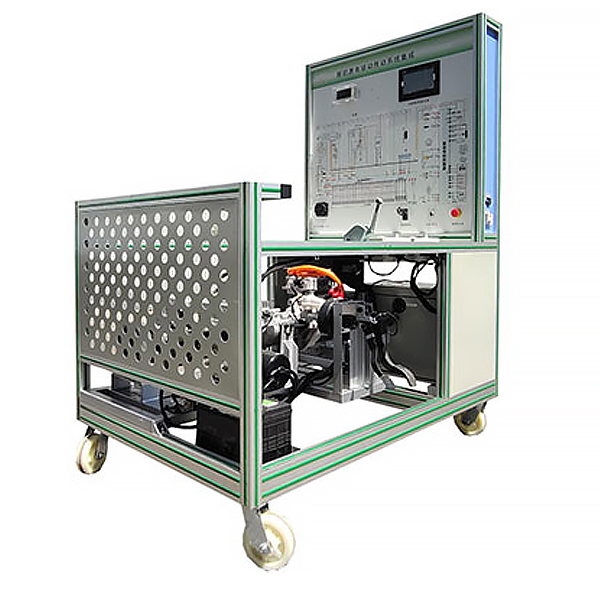
DYXNYQD-15 Electric Vehicle Electric Drive Transmission System Experimental Device
Release time:2024-05-25 20:30viewed:times
1. Product introduction:
Select pure electric vehicle AC asynchronous motor and controller, intelligent working condition simulation system, lithium battery and management system (BMS), instrument, transmission system, electronic vacuum hydraulic braking system, simulated loading controller, loader, Experimental tr*ning benches made of real devices such as teaching boards can complete experimental tr*ning content related to power drive systems. Suitable for disassembly, assembly and m*ntenance, structural and principle understanding, system operation, functional dynamic demonstration, fault detection and diagnosis of electric drive transmission systems, lithium batteries and management systems (BMS) and other system theory and m*ntenance tr*ning in various colleges and universities. teaching needs.
2. Functional features
1. Lithium battery and management system (BMS): Power battery parameters perform real-time monitoring, fault diagnosis, SOC estimation, short-circuit protection, insulation detection, charge and discharge control, equalization and other functions, and communicate with the band through the CAN bus CAN communication vehicle chargers, etc. carry out information exchange.
2. Pure electric vehicle power battery pack (power battery: single lithium iron phosphate battery 3.2V50Ah, a total of 24 cells in series). The battery management system includes: voltage, temperature and current acquisition module, m*n control module, etc. The m*n control module passes CAN The network communicates with other modules and intuitively understands the power battery PACK technology.
3. The power battery pack, Hall current sensor , charging relay, discharge relay, precharge relay, total positive relay, and total negative relay are all equipped with detection ports, which can detect the electrical signals of system circuit components in real time, such as resistance, voltage, and current. , frequency signal, etc.
4. The BMS battery management system has a passive balancing function and switch control protection (single disconnection, short circuit, overvoltage, undervoltage, overcurrent, overtemperature), communicates with the vehicle charger via CAN, and controls the operation of the vehicle charger through BMS. , estimate SOC (state of charge), etc.
(1) It has single voltage data collection , total voltage data collection, current collection, and temperature collection.
(2) It has complete fault level alarm functions, including voltage, current, temperature and other fault alarms.
(3) It has SOC estimation function.
(4) It has charge and discharge control function.
(5) It has passive equilibrium management function.
(6) System switch passive mechanical contacts.
5. The power battery pack display (7-inch touch screen) is installed on the panel, and various parameters of the charging and discharging process can be observed (displaying the real-time voltage and temperature of each power battery, discharge and charging conditions, bus current, insulation conditions, etc.) Management information), which can display the control logic of the charging and discharging process of the power battery pack and the changing rules of the m*n component parameters. (It is equipped with BMS upper computer detection and calibration software that can operate normally).
6. Use real components of pure electric vehicle electric drive transmission systems (including motors and controllers, single-stage transmissions, electronic vacuum hydraulic braking, transmission and other systems) to achieve functional testing and experimental tr*ning of electric vehicle electric drive systems, including High and low speed control, braking, forward function, reverse function, charging function, interlock function, simulated loading load adjustment, etc.
7. Implement functional testing and experimental tr*ning for electric vehicle electric drive systems. Including three-phase winding DC resistance, phase-to-phase insulation, ground insulation, overload capacity, mechanical characteristics, etc.
8. Realize real-time monitoring experimental tr*ning of electric vehicle electric drive system. The upper computer software can display the changing relationship of motor speed, voltage, current, torque and other parameters under the vehicle's
constant speed, acceleration and deceleration conditions. 9. Intelligent working condition simulation system: The adjustable tension controller is used to simulate load changes and switch to simulate different working conditions of electric vehicles (starting, idling, constant speed, acceleration, deceleration, parking and climbing, etc.).
10. The motor controller and the BMS control unit have a diagnostic interface, and the system data flow information (including brake switch, gear position, motor speed, voltage and current, motor temperature, motor torque, electronic throttle opening, busbar, etc.) can be read through the host computer software. terminal voltage/current, motor controller output terminal voltage/current, braking energy recovery and other working status; battery pack voltage value, charge and discharge current, temperature, etc.) and fault content.
11. The multi-functional instrument displays vehicle speed, voltage, gear, current, battery status parameters, etc. in real time.
12. The panel is made of 4mm thick aluminum-plastic plate, and the vertically installed panel is UV flatbed inkjet printed with a color complete standard system drawing board; students can visually compare the drawing board and the actual object to understand and analyze the working principle of the system.
13. There are detection terminals installed on the panel, which can directly detect the electrical signals of system circuit components on the panel, such as resistance, voltage, current, frequency signals, etc.
14. The installation of a fault simulation system can realize fault setting and diagnosis and elimination of low-voltage circuit systems. It can set up 15 common fault settings and assess fault points.
15. The equipment frame is constructed of two integrated all-aluminum alloy profiles, 40mm×40mm and 40mm×80mm. It is oil-resistant, corrosion-resistant and easy to clean. The table is 40CM wide, durable and rust-free, and has 4 swivel casters with self-locking devices. , easy to move.
16. Supporting teaching materials such as practical tr*ning (experiment) instructions, including working principles, practical tr*ning projects, fault settings and analysis and other key points.
17. Install safety protection devices: emergency stop switch, mechanical m*n power switch, m*ntenance switch, protective cover for rotating parts, high-voltage safety protection devices and warning prompts.
18. Mechanical assembly and fitter assembly virtual simulation software: This software is developed based on unity3d, with optional 6-level image quality. It is equipped with the design and virtual disassembly and assembly of reducers and shafting structures, the design and simulation of common mechanical mechanisms, and a mechanism resource library. For a typical mechanical mechanism (virtual disassembly and assembly of a gasoline engine), the software is a whole software and cannot be individual resources.
A. Reducer design and virtual disassembly interface can choose worm gear bevel gear reducer, two-stage expanded cylindrical gear reducer, bevel cylindrical gear reducer, coaxial cylindrical gear reducer, bevel gear reducer, and one-stage cylindrical gear reducer. Gear reducer.
Worm bevel gear reducer: After entering the software, the assembly content is automatically played. Each step in the video has a text description
. Secondary expandable cylindrical gear reducer: After entering the software, the content is played in the form of a video. The video content should include: Part name ( Scan the QR code to see the names of parts), disassembly and assembly demonstration (including disassembly and assembly), virtual disassembly (including overall, low-speed shaft, medium-speed shaft, high-speed shaft, box cover, box seat)
conical cylindrical gear reducer, Coaxial cylindrical gear reducer, bevel gear reducer, first-level cylindrical gear reducer: click to enter and automatically jump to the edrawings interface. The models are all three-dimensional models . By clicking on the parts, the names of the parts are displayed, and the 360° view is av*lable Rotate, enlarge, reduce, translate, and at the same time, the entire reducer can be disassembled and assembled through the moving parts function. At the same time, you can select the home button to return to the original state of the reducer. The bevel gear reducer and first-stage cylindrical gear reducer have added the function of inserting a cross section, and the cross section can be freely dragged to observe the internal structure of the reducer.
B. Shaft structure design and virtual disassembly and assembly interface optional parts recognition, disassembly and assembly demonstration, and actual operation.
1. Parts recognition: three-dimensional model and part name including helical gear, non-hole end cover, coupling, coupling key, shaft, gear key, hole end cover, shaft sleeve, deep groove ball bearing, any All parts can be rotated 360°
2. Disassembly and assembly demonstration: There are 2 built-in cases. When you move the mouse to the position of a cert*n part (except the base and bearing seat), the part will automatically enlarge and the name of the part will be displayed. It is equipped with disassembly and Assembly button, the function is to automatically complete the disassembly and assembly of the shaft system structure by the software. All three-dimensional scenes can be rotated, enlarged, reduced and translated 360° in all directions.
3. Practical operation: The three-dimensional parts are neatly placed on the table. Students manually select the corresponding parts and move them to the shaft system structure. The parts can be installed only when they are placed in the correct order and in the correct position. There is a restart button to facilitate students to restart. Conduct virtual experiments. When you move the mouse to a cert*n part position (except the base and bearing seat), the part will automatically enlarge and the part name will be displayed.
C. Common mechanical mechanism design and simulation, optional hinge four-bar mechanism design and analysis, I\II type crank rocker mechanism design and analysis, offset crank slider mechanism design and analysis, crank swing guide rod mechanism design and analysis, hinge Four-bar mechanism with integrated trajectory, eccentric linear-acting roller push rod cam , and centering linear-acting flat-bottomed push rod cam .
1. Each mechanism should be able to input corresponding parameters, and the software can automatically calculate the parameters, and can perform motion simulation and automatically draw curves.
D. The mechanism resource library includes 11 types of planar link mechanisms, 5 types of cam mechanisms, 6 types of gear mechanisms, 8 types of transmission mechanisms, 11 types of tightening mechanisms, 6 types of gear tr*n mechanisms, and 8 types of other mechanisms (mechanical equipment simulation)
E , virtual disassembly and assembly of gasoline engines, optional crankcase assembly and disassembly demonstration, crankcase virtual assembly, valve tr*n assembly and disassembly demonstration, valve tr*n virtual assembly
1, crankcase assembly and disassembly demonstration and valve tr*n assembly and disassembly demonstration both have disassembly button, assembly button, restart, and decomposition observation button. When the mouse is moved to a cert*n part position, the part will automatically enlarge and the part name will be displayed. The software automatically completes the disassembly and assembly of the shaft system structure. When the decomposition observation button is used, the 3D model of the crankcase or gas distribution system automatically displays an exploded view, which can be rotated, enlarged, reduced, and translated 360°.
2. The 3D parts of the crankcase virtual assembly and the gas distribution system virtual assembly are neatly arranged When placed on the desktop, students manually select the corresponding parts and move them to the mechanism. The parts can be installed only when they are placed in the correct order and in the correct position. There is a restart button to facilitate students to re-perform the virtual experiment. When you move the mouse to cert*n part locations, the part names are automatically displayed.
3. Technical specifications
1. Overall dimensions (mm): 1500×1000×1700 (length×width×height)
2. Panel dimensions (mm): 948×898mm (length*width)
3. Mobile casters: 100*60mm
4 .Operating temperature: -40℃~+50℃
5. Charging input power supply: AC220V±10%50Hz;
6. Auxiliary battery: 12V45AH;
7. Power battery type: lithium iron phosphate power battery (single battery 3.2V50AH, 24 strings )
8. Battery pack management system (BMS): with CAN communication;
9. Power battery pack display: 7-inch touch screen;
10. High voltage and high current relay: coil voltage: 12VDC, maximum rated working voltage: 1000VDC, rated current: 400A ;
11. AC asynchronous motor drive system: 5KW72VDC, 16Nm, 3000r/min, protection level: IP54, natural *r cooling;
12. Gearbox: single-stage helical gear transmission , total reduction ratio 1:16.7; operating noise is less than 70 decibels;
13. Simulated load device: Magnetic powder brake: PBS-20 (with adjustable tension controller), rated torque: 20N.m;
4. Practical tr*ning items
1. Power battery pack PACK assembly and connection method, lithium iron phosphate power battery Pack structure and principle, common fault judgment and rep*r methods of power battery pack;
2. Internal structure and principle of high voltage and high current relay, measurement of high voltage and high current relay, common faults and replacement methods of high voltage and high current relay;
3. Hall current sensor measurement, Hall current sensor common faults and replacement;
4. Manual m*ntenance switch structure principle and function;
5. High voltage interlock structure principle and function;
6. Vehicle charger working principle and pin definition, common faults and replacement of vehicle charger;
7.DC - Working principle and pin definition of DC converter, common faults and replacement of DC-DC conversion;
8. Structural principles and functions of battery management system BMS;
9. Structural principles and functions of motor drive system, measurement of motor drive system, common faults of motor drive system and Method of exclusion;
10. The working principle and pin definitions of the electronic accelerator pedal, common faults and replacement of the electronic accelerator pedal;
11. The working principle and pin definitions of the electric vacuum pump, common faults and replacement of the electric vacuum pump, the working principle and pin definitions of the vacuum pressure sensor module, vacuum Common faults of the pressure sensor module and replacement methods;
12. Structural principles and functions of the brake energy recovery system;
13. The changing relationship of motor speed, voltage, current, torque and other parameters when the motor is operating at a constant speed of the vehicle.
14. The relationship between the changes in motor speed, voltage, current, torque and other parameters when the motor is accelerating the vehicle.
15. The relationship between the changes in motor speed, voltage, current, torque and other parameters when the motor is decelerating the vehicle.
16. Trouble analysis and troubleshooting when the motor does not rotate.
5. Basic configuration of
lithium iron phosphate power battery pack and management system (with CAN communication, including 24 cells, discharge relay, charging relay, precharge relay, precharge resistor, Hall current sensor, m*ntenance switch, fuse, charging interface , discharge interface, low-voltage control interface, power battery acquisition module, BMS battery management system m*n control module, 7-inch LCD screen), drive motor and operating part, electronic throttle assembly, shift mechanism assembly, instrument (with CAN communication ), gearbox, left and right drive shafts, left and right front wheel disc brakes, magnetic powder brakes (left and right), manual tension controller, booster pump assembly, vacuum pump assembly, electric vacuum booster brake system, vacuum pressure sensor, vacuum tank assembly Complete, national standard charging socket and charging gun, vehicle charger (with CAN communication), DC-DC module, fault setting system, auxiliary battery (12V45AH), battery power-off switch, emergency stop switch, host computer software and data cable (motor and battery control unit), integrated all-aluminum alloy profile mobile stand (1500×1000×1700mm, with self-locking caster device, 948×898mm principle panel with installed detection terminals), fault assessment system, and equipment operating instructions.


 Wechat scan code follow us
